 English
 Espaol
 Franais
 阿拉伯
阿拉伯 中文(簡)
中文(簡) Deutsch
 Italiano
 Português
 日本
日本 韓國
韓國 български
 hrvatski
 esky
esky Dansk
Dansk Nederlands
 suomi
suomi Ελληνικ
 印度
印度 norsk
norsk Polski
 Roman
Roman русский
 Svenska
 珀金斯Perkins1600發動機維修拆卸組裝手冊,珀金斯Perkins1600發動機維修拆卸組裝手冊技術支持中心,珀金斯Perkins1600發動機維修拆卸組裝手冊代理商,珀金斯Perkins1600發動機維修拆卸組裝手冊銷售服務中心,珀金斯Perkins1600發動機維修拆卸組裝手冊價格規格資料查詢,寧波日昕動力科技有限公司

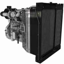
珀金斯Perkins1600發動機維修拆卸組裝手冊
詳細描述
Disassembly and
Assembly
1600 Series Industrial Engine
XGA (Engine)
XGB (Engine)
XGD (Engine)
XGE (Engine)
XGF (Engine)
XGH (Engine)
This document is printed from SPI². Not for RESALE
![]()
![]()
![]()

Important Safety Information
Most accidents tha t involve produc t op eration, ma intena nc e and repair are caus ed by failure to
ob serve basic safety rules or precautions . An accident can often be avoided by recog nizing pote ntially
ha za rdous situations before an accident oc curs . A person mus t be alert to pote ntial ha za rds. This
person should also ha ve the ne cessary training, skills and tools to perform the se func tions properly.
Improper operation, lubrication, maintenance or repair of this product can be dangerous and
could result in injury or death.
Do not operate or perform any lubrication, maintenance or repair on this product, until you have
read and understood the operation, lubrication, maintenance and repair information.
Sa fety precautions and warning s are provided in this ma nua l and on the produc t. If the se ha za rd
warning s are not he eded, bod ily injury or death could oc cur to you or to othe r persons .
The ha za rds are identified by the “Safety Alert Symb ol” and followed by a “Signa l Word” suc h as
“DANGER”, “WARNING” or “CAUTION”. The Sa fety Alert “WARNING” label is shown below.
The me aning of this safety alert symb ol is as follows:
Attention! Become Alert! Your Safety is Involved.
The me ssage tha t appears und er the warning explains the ha za rd and can be either written or
pictorially presente d.
Op erations tha t ma y caus e produc t dama ge are identified by “NOTICE” labels on the produc t and in
this pub lication.
Perkins cannot anticipate every possible circumstance that might involve a potential hazard. The
warnings in this publication and on the product are, therefore, not all inclusive. If a tool, procedure,
work method or operating technique that is not specifically recommended by Perkins is used,
you must satisfy yourself that it is safe for you and for others. You should also ensure that the
product will not be damaged or be made unsafe by the operation, lubrication, maintenance or
repair procedures that you choose.
The informa tion, specifications , and illustrations in this pub lication are on the basis of informa tion tha t
was available at the time tha t the pub lication was written. The specifications , torque s, pressure s,
me asure me nts , adjustme nts , illustrations , and othe r items can cha ng e at any time. These cha ng es can
affect the service tha t is given to the produc t. Ob tain the comp lete and mos t current informa tion before
you start any job. Pe rkins dealers or Pe rkins distributors ha ve the mos t current informa tion available.
When replacement parts are required for this
product Perkins recommends using Perkins
replacement parts.
Failure to heed this warning can lead to prema-
ture failures, product damage, personal injury or
death.
This document is printed from SPI². Not for RESALE
![]()
![]()
KENR8773
3
Table of Contents
Table of Contents
Inlet and Exhaust Valve Springs - Remove and Install
(1606A and 1606D Engines) ............................... 67
Inlet and Exhaust Valves - Remove and Install
(1606A and 1606D Engines) ............................... 70
Inlet and Exhaust Valve Guides - Remove and Install
(1606A and 1606D Engines) ............................... 72
Engine Centrifugal Oil Filter - Remove and Install
(1606D Engines) ................................................. 74
Engine Oil Filter Base - Remove (1606A and 1606D
Engines) .............................................................. 77
Engine Oil Filter Base - Disassemble (1606A and
1606D Engines) .................................................. 79
Engine Oil Filter Base - Assemble (1606A and 1606D
Engines) .............................................................. 80
Engine Oil Filter Base - Install (1606A and 1606D
Engines) .............................................................. 82
Engine Oil Cooler - Remove (1606A and 1606D
Engines) .............................................................. 84
Engine Oil Cooler - Install (1606A and 1606D
Engines) .............................................................. 85
Engine Oil Temperature Regulator - Remove and
Install (1606A and 1606D Engines) .................... 86
Engine Oil Relief Valve - Remove and Install (1606A
and 1606D Engines) ........................................... 87
Engine Oil Pump - Remove (1606A and 1606D
Engines) .............................................................. 88
Engine Oil Pump - Install (1606A and 1606D
Disassembly and Assembly Section
Fuel Filter Base - Remove (1606A and 1606D
Engines) ................................................................ 5
Fuel Filter Base - Disassemble (1606A and 1606D
Engines) ................................................................ 6
Fuel Filter Base - Assemble (1606A and 1606D
Engines) ................................................................ 8
Fuel Filter Base - Install (1606A and 1606D
engines) .............................................................. 10
Switch (Water in Fuel) - Remove and Install (1606A
and 1606D Engines) ........................................... 12
Fuel Transfer Pump - Remove (1606A and 1606D
Engines) .............................................................. 12
Fuel Transfer Pump - Install (1606A and 1606D
Engines) .............................................................. 14
Exhaust Gas Recirculation Cooler - Remove and
Install (1606D Engines) ....................................... 16
Electronic Unit Injector - Remove (1606A and 1606D
Engines) .............................................................. 18
Electronic Unit Injector - Install (1606A and 1606D
Engines) .............................................................. 19
Electronic Unit Injector Sleeve - Remove (1606A and
1606D Engines) .................................................. 21
Electronic Unit Injector Sleeve - Install (1606A and
1606D Engines) .................................................. 22
Injection Actuation Pressure Control Valve - Remove
and Install (Injection Pressure Regulator (IPR) Valve
for 1606A and 1606D Engines) ........................... 23
Injection Actuation Pressure Control Sensor
Engines) .............................................................. 90
Water Pump - Remove (1606A and 1606D
Engines) .............................................................. 92
Water Pump - Install (1606A and 1606D
Engines) .............................................................. 93
Water Temperature Regulator Housing - Remove and
Install (1606A and 1606D Engines) .................... 94
Engine Support (Front) - Remove and Install (1606A
and 1606D Engines) ........................................... 95
Flywheel - Remove (1606A and 1606D Engines) .. 96
Flywheel - Install (1606A and 1606D Engines) ..... 97
Crankshaft Rear Seal - Remove (1606A and 1606D
Engines) .............................................................. 99
Crankshaft Rear Seal - Install (1606A and 1606D
Engines) ............................................................ 100
Flywheel Housing - Remove and Install (1606A and
1606D Engines) ................................................ 101
Vibration Damper and Pulley - Remove and Install
(1606A and 1606D Engines) ............................. 104
Crankshaft Front Seal - Remove (1606A and 1606D
Engines) ............................................................ 107
Crankshaft Front Seal - Install (1606A and 1606D
Engines) ............................................................ 108
Front Cover - Remove (1606A and 1606D
- Remove and Install (1606A and 1606D
Engines) .............................................................. 24
Unit Injector Hydraulic Pump - Remove and Install
(1606A and 1606D Engines) ............................... 25
Unit Injector Hydraulic Pump Gear - Remove and
Install (1606A and 1606D Engines) .................... 30
Unit Injector Actuation Oil Manifold - Remove and
Install (1606A and 1606D Engines) .................... 31
Air Cleaner - Remove and Install (1606A and 1606D
Engines) .............................................................. 36
Turbocharger - Remove (1606D Engines) ............ 38
Turbocharger - Remove (1606A Engines) ............ 39
Turbocharger - Install (1606D Engines) ................ 40
Turbocharger - Install (1606A Engines) ................ 42
Exhaust Gas Recirculation Valve - Remove and
Install (1606D Engines) ....................................... 44
Exhaust Manifold - Remove (1600D Engines) ...... 47
Exhaust Manifold - Remove (1606A Engines) ...... 50
Exhaust Manifold - Install (1600D Engines) .......... 52
Exhaust Manifold - Install (1606A Engines) .......... 56
Pressure Sensor (Exhaust Manifold) - Remove and
Install (1600D Engine) ........................................ 59
Exhaust Elbow - Remove and Install (1606A and
1606D Engines) .................................................. 61
Air Inlet Heater - Remove and Install (1606A and
1606D Engines) .................................................. 61
Inlet Manifold - Remove and Install (1606A and
1606D Engines) .................................................. 63
Engines) ............................................................. 110
Front Cover - Install (1606A and 1606D
Engines) ............................................................. 113
Gear Group (Front) - Remove (1606A and 1606D
Engines) ............................................................. 117
Gear Group (Front) - Install (1606A and 1606D
Engines) ............................................................. 118
Housing (Front) - Remove (1606A and 1606D
Engines) ............................................................. 119
Housing (Front) - Install (1606A and 1606D
Engines) ............................................................ 122
This document is printed from SPI². Not for RESALE
![]()
4
KENR8773
Table of Contents
Crankcase Breather - Remove and Install (1606A
and 1606D Engines) ......................................... 125
Valve Mechanism Cover - Remove and Install (1606A
and 1606D Engines) ......................................... 129
Rocker Shaft and Pushrod - Remove (1606A and
1606D Engines) ................................................ 136
Rocker Shaft - Disassemble (1606A and 1606D
Engines) ............................................................ 137
Rocker Shaft - Assemble (1606A and 1606D
Engines) ............................................................ 138
Rocker Shaft and Pushrod - Install (1606A and
1606D Engines) ................................................ 139
Cylinder Head - Remove (1606A and 1606D
Engine Oil Pressure Sensor - Remove and Install
(1606A and 1606D Engines) ............................. 189
Engine Oil Temperature Sensor - Remove and Install
(1606A and 1606D Engines) ............................. 190
Fuel Pressure Sensor - Remove and Install (1606A
and 1606D Engines) ......................................... 192
Inlet Manifold Temperature Sensor - Remove and
Install (1606A and 1606D Engines) .................. 193
Inlet Manifold Pressure Sensor - Remove and Install
(1606A and 1606D Engines) ............................. 194
Jacket Water Heater - Remove and Install (1606A
and 1606D Engines) ......................................... 195
Alternator Belt - Remove and Install (1606A and
1606D Engines) ................................................ 196
Belt Tensioner - Remove and Install (1606A and
1606D Engines) ................................................ 197
Fan - Remove and Install (1606A and 1606D
Engines) ............................................................ 141
Cylinder Head - Install (1606A and 1606D
Engines) ............................................................ 144
Lifter Group - Remove (1606A and 1606D
Engines) ............................................................ 147
Lifter Group - Install (1606A and 1606D
Engines) ............................................................ 148
Camshaft - Remove (1606A and 1606D
Engines) ............................................................ 148
Camshaft - Install (1606A and 1606D Engines) .. 150
Camshaft Gear - Remove and Install (1606A and
1606D Engines) ................................................ 152
Camshaft Bearings - Remove and Install (1606A and
1606D Engines) ................................................ 153
Engine Oil Pan - Remove and Install (1606A and
1606D Engines) ................................................ 155
Cylinder Liner - Remove (1606A and 1606D
engines) ............................................................ 198
Fan Drive - Remove and Install (1606A and 1606D
Engines) ............................................................ 199
Electronic Control Module - Remove and Install
(1606A and 1606D Engines) ............................. 201
Alternator - Remove and Install (1606A and 1606D
Engines) ............................................................ 204
Electric Starting Motor - Remove and Install (1606A
and 1606D Engines) ......................................... 206
Index Section
Index ................................................................... 207
Engines) ............................................................ 159
Cylinder Liner - Install (1606A and 1606D
Engines) ............................................................ 160
Piston Cooling Jets - Remove and Install (1606A and
1606D Engines) ................................................ 162
Pistons and Connecting Rods - Remove (1606A and
1606D Engines) ................................................ 163
Pistons and Connecting Rods - Disassemble (1606A
and 1606D Engines) ......................................... 164
Pistons and Connecting Rods - Assemble (1606A
and 1606D Engines) ......................................... 166
Pistons and Connecting Rods - Install (1606A and
1606D Engines) ................................................ 168
Crankshaft Main Bearings - Remove (1606A and
1606D Engines with Crankshaft in Position) ..... 170
Crankshaft Main Bearings - Install (1606A and 1606D
Engines with Crankshaft in Position) ................ 171
Crankshaft - Remove (1606A and 1606D
Engines) ............................................................ 174
Crankshaft - Install (1606A and 1606D
Engines) ............................................................ 176
Crankshaft Timing Ring - Remove and Install (1606A
and 1606D Engines) ......................................... 181
Crankshaft Gear - Remove and Install (1606A and
1606D Engines) ................................................ 182
Bearing Clearance - Check ................................. 184
Camshaft Position Sensor - Remove and Install
(1606A and 1606D Engines) ............................. 185
Crankshaft Position Sensor - Remove and Install
(1606A and 1606D Engines) ............................. 186
Coolant Temperature Sensor - Remove and Install
(1606A and 1606D Engines) ............................. 187
This document is printed from SPI². Not for RESALE
![]()
KENR8773
5
Disassembly and Assembly Section
Disassembly and Assembly
Section
i04638569
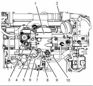
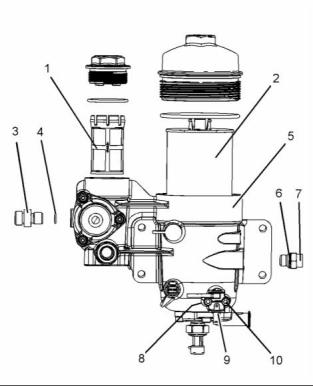
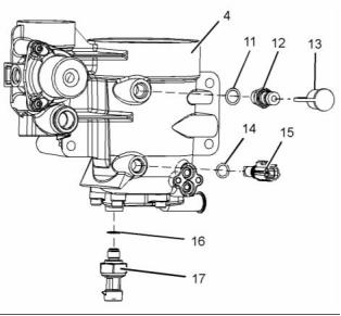
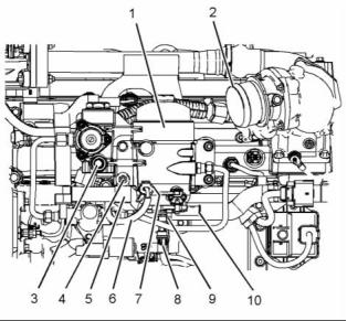
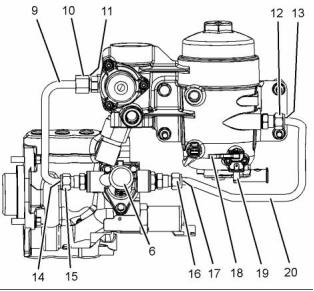
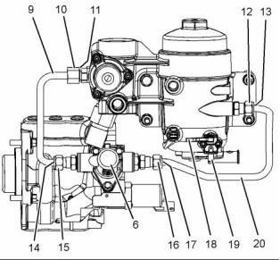
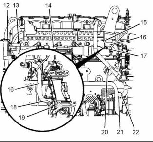
Fuel Filter Base - Remove
(1606A and 1606D Engines)
Removal Procedure
Table 1
Required Tools
Tool
Part Number
Part Description
Capping Kit
Qty
A
29990075
1
g02797418
NOTICE
Illustration 1
Ensure that all adjustments and repairs that are
carried out to the fuel system are performed by
authorized personnel that have the correct train-
ing.
3. If necessary, disconnect hose assembly from inlet
connection (2).
4. Drain the fuel from fuel filter base (1). Refer to
the Operation and Maintenance Manual, “Fuel
System Primary Filter/Water Separator - Drain” for
the correct procedure.
Before beginning ANY work on the fuel system, re-
fer to Operation and Maintenance Manual, “Gen-
eral Hazard Information and High Pressure Fuel
Lines” for safety information.
5. Disconnect the fuel hose assembly from inlet
connection (3) on fuel filter base (1).
Refer to System Operation, Testing and Adjusting,
“Cleanliness of Fuel System Components” for de-
tailed information on the standards of cleanliness
that must be observed during ALL work on the fu-
el system.
6. Use Tooling (A) in order to plug the fuel hose
assembly. Use Tooling (A) in order to cap
connection (3).
7. Disconnect fuel hose assembly from return
connection (10) on fuel filter base (1).
1. Turn the fuel supply to the OFF position.
2. Turn the battery disconnect switch to the OFF
position.
8. Use Tooling (A) in order to plug the fuel hose
assembly. Use Tooling (A) in order to cap
connection (10).
9. Disconnect harness assembly (6) from water in
fuel sensor (7) (not shown).
10. Disconnect harness assembly (8) from fuel
pressure sensor (9).
11. Remove nut (4) and disconnect harness assembly
(5) from the stud bolt on fuel filter base (1).
This document is printed from SPI². Not for RESALE
![]()
![]()
![]()
![]()
6
Disassembly and Assembly Section
KENR8773
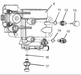
g03158102
g03158357
Illustration 2
Illustration 3
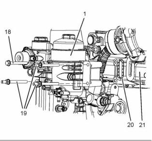
12. Disconnect tube assembly (11) from fuel filter
base (1) and fuel transfer pump (14).
22. Remove bolt (18) and stud bolts (19) from fuel
filter base (1). Support the fuel filter base as the
bolts are removed.
13. Remove O-ring seal (12) (not shown) from the
connection on fuel filter base (1).
Note: Note the position of the different length bolts
and different types of bolts for installation purposes.
14. Use Tooling (A) in order to cap the connection on
fuel filter base (1).
23. Remove fuel filter base (1) from inlet manifold
(21).
15. Use Tooling (A) in order to cap fuel transfer pump
(14).
24. Remove gasket seal (20).
16. Remove seal (13) (not shown) from tube
assembly (11).
i04638591
Fuel Filter Base - Disassemble
(1606A and 1606D Engines)
17. Use Tooling (A) in order to cap tube assembly
(11).
18. Disconnect tube assembly (16) from fuel filter
base (1) and fuel lift pump (14).
Disassembly Procedure
19. Remove seal (15) (not shown) and seal (17) (not
shown) tube assembly (16).
Start By:
20. Use Tooling (A) in order to cap tube assembly
(16).
a. Remove the fuel filter base. Refer to Disassembly
and Assembly, “Fuel Filter Base - Remove”.
21. Use Tooling (A) in order to cap the connection on
fuel filter base (1) and fuel lift pump (14).
This document is printed from SPI². Not for RESALE
![]()
![]()
![]()

KENR8773
7
Disassembly and Assembly Section
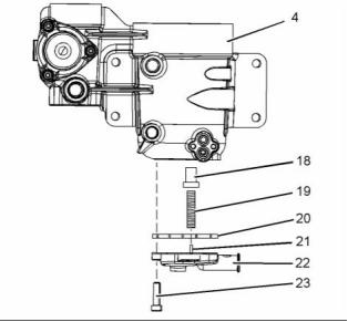
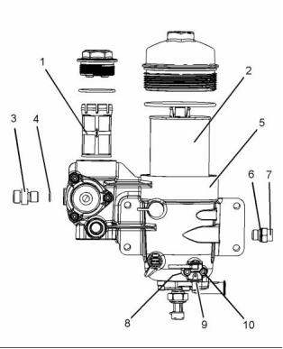
5. Remove Torx screws (10). Remove drain valve (9)
assembly from fuel filter base (4).
NOTICE
Ensure that all adjustments and repairs that are
carried out to the fuel system are performed by
authorized personnel that have the correct train-
ing.
6. Remove O-ring (8) (not shown).
Before beginning ANY work on the fuel system, re-
fer to Operation and Maintenance Manual, “Gen-
eral Hazard Information and High Pressure Fuel
Lines” for safety information.
Refer to System Operation, Testing and Adjusting,
“Cleanliness of Fuel System Components” for de-
tailed information on the standards of cleanliness
that must be observed during ALL work on the fu-
el system.
g02797583
Illustration 5
7. Use a deep socket in order to remove fuel pressure
sensor (14) from fuel filter base assembly (4).
8. Remove O-ring seal (16) from the fuel pressure
sensor.
9. Use a suitable tool in order to remove water in fuel
sensor (15) from fuel filter base assembly (4).
10. Remove O-ring seal (16) from the water in fuel
sensor.
11. Remove dust cap (13) from fuel sampling valve
(12).
12. Use a deep socket in order to remove fuel
sampling valve (12) from fuel filter base assembly
(4).
g02797498
Illustration 4
13. Remove O-ring seal (5) from the fuel sampling
valve.
1. Remove primary fuel filter (1). Refer to the
Operation and Maintenance Manual, “Fuel System
Primary Filter - Clean/Inspect/Replace” for the
correct procedure.
Personal injury can result from being struck by
parts propelled by a released spring force.
2. Remove secondary fuel filter (2). Refer to the
Operation and Maintenance Manual, “Fuel
System Secondary Filter - Replace” for the correct
procedure.
Make sure to wear all necessary protective equip-
ment.
3. Remove connection (3) from fuel filter base (4).
Remove O-ring (4) from the connection.
Follow the recommended procedure and use all
recommended tooling to release the spring force.
4. Remove connection (7) from fuel filter base (4).
Remove O-ring (6) from the connection.
This document is printed from SPI². Not for RESALE
![]()
![]()
![]()
![]()
![]()
![]()
![]()
8
Disassembly and Assembly Section
KENR8773
1. Ensure that the fuel filter base is clean, free from
restriction, and free from damage. If necessary,
replace the complete fuel filter base and filter
assembly.
g03159778
Illustration 6
14. Remove Torx screws (23). Support cover plate
(22) as the Torx screws are loosened.
g03159778
Illustration 7
15. Remove cover plate (22), spring (19), and valve
(18) from fuel filter housing (4).
2. Install a new gasket seal (20) to cover plate (22).
Ensure that the gasket seal is correctly seated
into the recess in the cover plate.
16. Ensure that spring locator (21) is not damaged.
17. Remove gasket seal (20).
3. Install valve (18) into fuel filter base (4). Ensure
that the valve is correctly installed into the fuel filter
housing. Ensure that the valve can freely move.
i04638611
Fuel Filter Base - Assemble
(1606A and 1606D Engines)
4. Install spring (19) into valve (18). Ensure that the
spring is correctly installed into the valve.
5. Position cover plate (22) onto spring (19). Ensure
that spring (19) is correctly located onto locator
(21) in the cover plate.
Assembly Procedure
6. Install Torx screws (23) to cover plate (22).
NOTICE
7. Tighten Torx screws (23) evenly in order to pull
cover plate (22) into position on fuel filter base (4).
Ensure that all adjustments and repairs that are
carried out to the fuel system are performed by
authorized personnel that have the correct train-
ing.
8. Tighten Torx screws (23) to a torque of 10 N·m
(89 lb in).
Before beginning ANY work on the fuel system, re-
fer to Operation and Maintenance Manual, “Gen-
eral Hazard Information and High Pressure Fuel
Lines” for safety information.
Refer to System Operation, Testing and Adjusting,
“Cleanliness of Fuel System Components” for de-
tailed information on the standards of cleanliness
that must be observed during ALL work on the fu-
el system.
This document is printed from SPI². Not for RESALE
![]()
![]()
![]()
![]()
![]()
KENR8773
9
Disassembly and Assembly Section
g02797583
Illustration 8
9. Install a new O-ring seal (16) from fuel pressure
sensor (17).
10. Install fuel pressure sensor (17) to fuel filter base
assembly (4).
g02797498
Illustration 9
11. Use a deep socket in order to tighten fuel pressure
sensor to a torque of 11 N·m (97 lb in).
17. Install a new O-ring (4) to connection (3).
18. Install connection (3) to fuel filter base (4). Tighten
the connection to a torque of 18 N·m (159 lb in).
12. Install a new O-ring seal (16) to the water in fuel
sensor.
19. Install a new O-ring (6) to connection (7).
13. Use a suitable tool in order to install water in fuel
sensor (15) to fuel filter base assembly (4). Tighten
the fuel sensor to a torque of 2 N·m (18 lb in).
20. Install connection (7) to fuel filter base (4). Tighten
the connection to a torque of 18 N·m (159 lb in).
14. Install a new O-ring seal (5) to fuel sampling valve
(12).
21. Install a new O-ring (8) (not shown) into recess
in fuel filter base (4). Position drain valve (9)
assembly to fuel filter base (4).
15. Use a deep socket in order to install fuel sampling
valve (12) to fuel filter base assembly (4). Tighten
the fuel sampling valve to a torque of 17 N·m
(150 lb in).
22. Install Torx screws (10) finger tight.
23. Tighten Torx screws (10) to a torque of 5 N·m
(44 lb in).
16. Install dust cap (13) to fuel sampling valve (12).
24. Ensure that drain valve (9) move freely after the
Torx screws have been tightened.
25. Install a new primary fuel filter (1). Refer to the
Operation and Maintenance Manual, “Fuel System
Primary Filter - Clean/Inspect/Replace” for the
correct procedure.
26. Install a new secondary fuel filter (2). Refer to
the Operation and Maintenance Manual, “Fuel
System Secondary Filter - Replace” for the correct
procedure.
This document is printed from SPI². Not for RESALE
![]()
![]()
![]()
10
KENR8773
Disassembly and Assembly Section
End By:
a. Install the fuel filter base. Refer to Disassembly
and Assembly, “Fuel Filter Base - Install”.
i04640250
Fuel Filter Base - Install
(1606A and 1606D engines)
Installation Procedure
NOTICE
Keep all parts clean from contaminants.
Contaminants may cause rapid wear and shortened
component life.
g03158357
Illustration 10
NOTICE
2. Position a new gasket seal (20) into the recess of
fuel filter base (1).
Ensure that all adjustments and repairs that are
carried out to the fuel system are performed by
authorized personnel that have the correct train-
ing.
3. Position fuel filter base (1) onto inlet manifold (21).
4. Install bolt (18) and stud bolts (19) to fuel filter
base (1). Support the fuel filter base as the bolts
are installed.
Before beginning ANY work on the fuel system, re-
fer to Operation and Maintenance Manual, “Gen-
eral Hazard Information and High Pressure Fuel
Lines” for safety information.
Note: Ensure that the different length bolts and
the different types of bolts are installed to the bolts
original position.
Refer to System Operation, Testing and Adjusting,
“Cleanliness of Fuel System Components” for de-
tailed information on the standards of cleanliness
that must be observed during ALL work on the fu-
el system.
5. Tighten bolt (18) and stud bolts (19) to a torque of
31 N·m (274 lb in).
1. Ensure that the fuel filter base is clean and free
from damage. If necessary, replace the complete
fuel filter base and filter assembly.
g03158102
Illustration 11
This document is printed from SPI². Not for RESALE
![]()
![]()
![]()
![]()
![]()
![]()
![]()
KENR8773
11
Disassembly and Assembly Section
6. Remove the caps from the connections on fuel
filter base (1) and fuel lift pump (14).
20. Remove the caps from fuel hose assembly and
the return connection (10) on fuel filter base (1).
7. Position a new O-ring seal (12) (not shown) onto
the connection on fuel filter base (1).
21. Connect the fuel hose assembly onto return
connection (10) on fuel filter base (1).
8. Remove the caps from tube assembly (11).
22. Position harness assembly (5) onto the stud bolt
on fuel filter base (1). Install nut (4) and tighten the
nut to a torque of 18 N·m (159 lb in). Ensure that
harness assembly (5) is not strained or twisted
as the nut are tightened.
9. Install a new seal (13) (not shown) to tube
assembly (11).
10. Connect tube assembly (11) to fuel filter base (1)
and fuel lift pump (14).
23. Connect harness assembly (6) onto the water in
fuel sensor (7) (not shown).
11. Tighten tube nut for tube assembly (11) on fuel
filter base (1) to a torque of 31 N·m (22 lb ft).
24. Connect harness assembly (8) onto fuel pressure
sensor (9).
12. Tighten tube nut on tube assembly (11) to a
torque of 18 N·m (159 lb in).
25. If necessary, install hose assembly to inlet
connection (2). Securely tighten hose clamps.
13. Remove the caps from the connections on fuel
filter base (1) and fuel lift pump (14).
26. Turn the battery disconnect switch to the ON
position.
14. Remove the caps from tube assembly (16).
27. Turn the fuel supply to the ON position.
15. Install new seal (15) (not shown) and new seal
(17) (not shown) to tube assembly (16).
End By:
16. Connect tube assembly (16) to fuel filter base (1)
and fuel lift pump (14).
a. Remove the air from the fuel system. Refer to
the Operation and Maintenance Manual, “Fuel
System - Prime” for the correct procedure.
17. Tighten tube nuts on tube assembly (16) to a
torque of 18 N·m (159 lb in).
g02797418
Illustration 12
18. Remove the caps from the fuel hose assembly
and inlet connection (3) on fuel filter base (1).
19. Connect the fuel hose assembly onto inlet
connection (3) on fuel filter base (1).
This document is printed from SPI². Not for RESALE
![]()
![]()
12
KENR8773
Disassembly and Assembly Section
i04893431
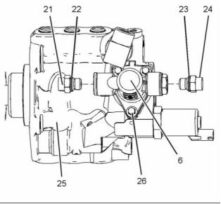
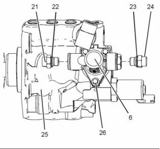
4. Connect harness assembly (6) to switch (5).
Switch (Water in Fuel) -
Remove and Install
(1606A and 1606D Engines)
End By:
a. Prime the fuel system. Refer to Operation and
Maintenance Manual, “Fuel System - Prime” for
the correct procedure.
Removal Procedure
i04640253
Fuel Transfer Pump - Remove
(1606A and 1606D Engines)
Removal Procedure
Table 2
Required Tools
Tool
Part Number
Part Description
Capping Kit
Qty
A
29990075
1
NOTICE
Care must be taken to ensure that fluids are contained
during performance of inspection, maintenance, test-
ing, adjusting and repair of the product. Be prepared to
collect the fluid with suitable containers before open-
ing any compartment or disassembling any compo-
nent containing fluids.
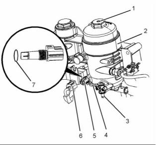
g03151157
Illustration 13
Dispose of all fluids according to local regulations and
mandates.
1. Ensure that fuel filter base (2) is clean and free
from dirt.
2. Attach a suitable tube onto drain (3). Loosen
cap (1) on fuel filter base (2) in order to allow
atmospheric pressure to act upon the fuel. Rotate
the cap three and a half turns in order to allow the
vent hole to be accessed.
NOTICE
Keep all parts clean from contaminants.
Contaminants may cause rapid wear and shortened
component life.
3. Open drain valve (4) and drain fuel from fuel filter
base (2). Close drain valve (4).
NOTICE
Ensure that all adjustments and repairs that are
carried out to the fuel system are performed by
authorized personnel that have the correct train-
ing.
4. Tighten cap (1) to a torque of 25 N·m (221 lb in)
5. Disconnect harness assembly (6) from switch (5).
6. Use a suitable tool in order to remove switch (5)
from fuel filter base (2).
Before beginning ANY work on the fuel system, re-
fer to Operation and Maintenance Manual, “Gen-
eral Hazard Information and High Pressure Fuel
Lines” for safety information.
7. Remove O ring seal (7) from switch (5).
Installation Procedure
Refer to System Operation, Testing and Adjusting,
“Cleanliness of Fuel System Components” for de-
tailed information on the standards of cleanliness
that must be observed during ALL work on the fu-
el system.
1. Install a new O ring seal (7) onto switch (5).
2. Use a suitable tool in order to install switch (5) into
fuel filter base (2).
1. Turn the battery disconnect switch to the OFF
3. Tighten switch (5) to a torque of 2 N·m (17 lb in).
position.
This document is printed from SPI². Not for RESALE
![]()
![]()
![]()
![]()
![]()
![]()
![]()
![]()
KENR8773
13
Disassembly and Assembly Section
2. Turn the fuel supply to the OFF position.
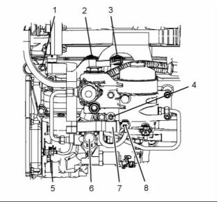
g03176033
Illustration 15
g03175857
Illustration 14
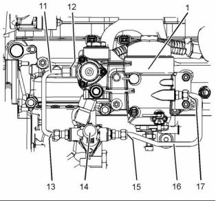
10. Attach a suitable tube onto drain (19). Loosen
the cap on the fuel filter base in order to allow
atmospheric pressure to act upon the fuel. Rotate
the cap three and a half turns in order to allow the
vent hole to be accessed.
3. Place a suitable container below fuel transfer
pump (6) in order to catch any fuel that might be
spilled.
4. Slide the locking tab into the unlocked position.
Disconnect harness assembly (2).
11. Open drain valve (18) and drain the fuel from the
fuel filter base. Close drain valve (18).
5. Slide the locking tab into the unlocked position.
Disconnect harness assembly (3).
12. Tighten the cap on the fuel filter base to a torque
of 25 N·m (221 lb in)
6. Remove nut (1) and nut (4) from harness
assembly (7).
13. Loosen tube nut (10) and tube nut (15) on tube
assembly (9) and drain the fuel from the system.
7. Disconnect harness assembly (8) from the water
in fuel sensor.
14. Loosen tube nut (12) and tube nut (16) on tube
assembly (20) and drain the fuel from the system.
8. Slide the locking tab into the unlocked position.
Disconnect harness assembly (5) from the engine
oil temperature sensor.
15. Remove tube assembly (9) and tube assembly
(20).
16. Remove O-ring seal (11) (not shown) from the
connection in the fuel filter base. Use Tooling (A) in
order to cap the connection in the fuel filter base.
9. Position harness assembly (7) away from transfer
pump (6).
17. Use Tooling (A) in order to cap the connections in
fuel transfer pump (6).
18. Remove seal (14) (not shown) from tube
assembly (9). Use Tooling (A) in order to cap tube
assembly (9)
19. Remove seal (13) (not shown) and seal (17) (not
shown) from tube assembly (20).
20. Use Tooling (A) in order to cap tube assembly (20)
This document is printed from SPI². Not for RESALE
![]()
![]()
![]()
14
KENR8773
Disassembly and Assembly Section
g03176216
g03176276
Illustration 16
Illustration 17
21. If necessary, follow Step 21.a through Step 21.f
in order to remove connections from fuel transfer
pump (6).
25. Remove O ring seal (27) from high-pressure oil
pump (25).
a. Remove connection (21) from fuel transfer
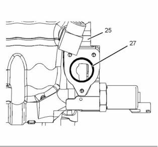
i04640255
pump (6).
Fuel Transfer Pump - Install
(1606A and 1606D Engines)
b. Remove O-ring seal (22) from connection (18).
c. Use Tooling (A) in order to cap connection (21).
d. Remove connection (24) from fuel transfer
pump (6).
Installation Procedure
NOTICE
Keep all parts clean from contaminants.
e. Remove O-ring seal (23) from connection (24).
f. Use Tooling (A) in order to cap connection (24).
Contaminants may cause rapid wear and shortened
component life.
22. Loosen evenly bolts (26) and remove bolts (26)
from transfer pump (6).
1. Ensure that the fuel transfer pump is clean and
free from damage.
23. Remove transfer pump (6) from high-pressure oil
pump (25)
24. Use Tooling (A) in order to plug high-pressure oil
pump (25).
This document is printed from SPI². Not for RESALE
![]()
![]()
![]()
![]()
![]()
KENR8773
15
Disassembly and Assembly Section
7. Install the connection to transfer pump (6). Tighten
connection (21) to a torque of 18 N·m (159 lb in).
8. Install a new O ring seal (23) to connection (24).
9. Install the connection to transfer pump (6). Tighten
connection (24) to a torque of 18 N·m (159 lb in).
g03176276
Illustration 18
2. Remove the plug from high-pressure oil pump
(25).
3. Position a new O-ring seal (27) into the recess of
high-pressure oil pump (25).
g03176033
Illustration 20
Note: Ensure that the O-ring seal is correctly seated
into the recess of the high-pressure oil pump.
10. Ensure that tube assembly (9) and tube assembly
(20) are clean, free damage, and free from
restriction.
11. Remove the cap from connection on the fuel filter
base. Install a new O-ring seal (11) (not shown)
to the connection.
12. Remove the caps from tube assembly (9). Ins, tall
a new seal (14) (not shown) to the tube assembly.
13. Install tube assembly (9) to transfer pump (6).
Tighten tube nut (10) and tube nut (15) for tube
assembly (9) hand tight.
14. Remove caps from tube assembly (20). Install
new seal (14) (not shown) and new seal (14) (not
shown) to the tube assembly.
15. Install tube assembly (20) to transfer pump (6).
Tighten tube nut (12) and tube nut (16) for tube
assembly (20) hand tight.
g03176216
Illustration 19
16. Tighten tube nut (10) to a torque of 31 N·m
(22 lb ft).
4. Position transfer pump (6) onto high-pressure oil
pump (25). Install bolts (26) and tighten the bolts
down evenly.
17. Tighten tube nut (15) to a torque of 18 N·m
(159 lb in).
5. Tighten bolts (26) to a torque of 13 N·m (115 lb in).
6. Install a new O ring seal (22) to connection (21).
18. Tighten tube nut (12) and tube nut (16) to a torque
of 18 N·m (159 lb in).
This document is printed from SPI². Not for RESALE
![]()
![]()

![]()
![]()
16
KENR8773
Disassembly and Assembly Section
i04893417
Exhaust Gas Recirculation
Cooler - Remove and Install
(1606D Engines)
Removal Procedure
1. Drain the coolant from the cooling system into
a suitable container for storage or disposal.
Refer to Operation and Maintenance Manual,
“Cooling System Coolant - Change” for the correct
procedure.
g03175857
Illustration 21
19. Position harness assembly (7) onto the stud bolts.
20. Install nut (1) and nut (4) hand tight.
21. Connect harness assembly (5) to the engine oil
temperature sensor. Slide the locking tab into the
locked position.
22. Connect harness assembly (8) to the water in fuel
sensor.
23. Tighten nut (1) to a torque of 18 N·m (159 lb in).
Ensure that harness assembly (7) is not strained
or twisted as the nut are tightened.
g03075897
Illustration 22
24. Tighten nut (4) to a torque of 18 N·m (159 lb in).
Ensure that harness assembly (7) is not strained
or twisted as the nut are tightened.
25. Connect harness assembly (2) and harness
assembly (3). Slide the locking tabs into the locked
position.
26. Prime the fuel system. Refer to Operation and
Maintenance Manual, “Fuel System - Prime”.
g03075903
Illustration 23
This document is printed from SPI². Not for RESALE
![]()
![]()
![]()

![]()

KENR8773
17
Disassembly and Assembly Section
2. Loosen hose clamp (2) and disconnect hose
assembly (1) from exhaust gas recirculation cooler
(3).
Note: The exhaust gas recirculation cooler
should not be disassembled or cleaned.
2. Ensure that the exhaust gas recirculation cooler is
free from wear and damage. If necessary, replace
exhaust gas recirculation cooler as an assembly.
3. Loosen the hose clamp for hose assembly (9).
4. Remove hose assembly (9) from exhaust gas
recirculation cooler (3).
3. Ensure that all tube assemblies are clean and
free from restriction, wear, and damage. If
necessary, replace any components that are worn
or damaged.
5. Remove bolt (6) and bolt (20) from tube assembly
(7).
6. Loosen hose clamp (22) for tube assembly (7).
7. Remove tube assembly (7) from valve mechanism
cover (5) and hose assembly (21). Remove O-ring
seal (8) (not shown) from tube assembly (7).
8. Prior to and during removal of bolts (11) apply
releasing fluid to the bolts.
9. Remove bolts (11) and remove gasket (10) (not
shown).
10. Prior to and during removal of bolts (13) apply
releasing fluid to the bolts.
11. Remove bolts (13).
12. Remove the nut from the assembly of clamp
(4). Position clamp (4) away from exhaust gas
recirculation cooler (3).
g03075897
Illustration 24
13. Remove the clamp plate from exhaust gas
recirculation cooler (3).
14. Remove bolt (17) from tube assembly (16).
15. Remove exhaust gas recirculation cooler (3) from
exhaust manifold (14) and tube assembly (16).
16. Remove gasket (12) (not shown) from exhaust
manifold (14).
17. Remove tube assembly (16) from front housing
(19).
18. Remove O-ring seal (15) (not shown) from O-ring
seal (18) (not shown) from tube assembly (16).
Installation Procedure
Table 3
Required Tools
g03075903
Illustration 25
Tool
Part Number
Part Description
Qty
A
CV60889
Anti-Seize Compound
1
4. Install a new O-ring seal (15) (not shown) and a
new O-ring seal (18) (not shown) to tube assembly
(16).
1. Ensure that the exhaust gas recirculation cooler is
clean and free from restriction. Refer to Systems
Operation, Testing and Adjusting, “Exhaust Cooler
(NRS) - Test” for the correct procedure.
This document is printed from SPI². Not for RESALE
![]()
![]()
![]()
18
KENR8773
Disassembly and Assembly Section
5. Install tube assembly (16) to front housing
(19). Ensure that the tube assembly is correctly
orientated and is fully installed to the front housing
22. Install a new O-ring seal (8) (not shown) to tube
assembly (7).
23. Install tube assembly (7) to valve mechanism
cover (5) and hose assembly (19). Ensure that
the tube assembly is correctly seated in to valve
mechanism cover (5) and hose assembly (19).
6. Position a new gasket (12) (not shown) onto
exhaust gas recirculation cooler (3). Ensure that
the gasket is correctly seated onto the exhaust
gas recirculation cooler.
24. Install bolt (6) and bolt (18) to tube assembly (7)
hand tight.
7. Position exhaust gas recirculation cooler (3) onto
exhaust manifold (14) and install tube assembly
(16) into exhaust gas recirculation cooler (3).
25. Tighten bolt (6) to a torque of 13 N·m (115 lb in).
26. Tighten bolt (18) to a torque of 62 N·m (45 lb ft).
Note: Ensure that the exhaust gas recirculation
cooler is correctly positioned onto the exhaust
manifold. Ensure that the tube assembly is correctly
seated into the exhaust gas recirculation cooler.
27. Securely tighten hose clamp (20).for tube
assembly (7).
8. Apply Tooling (A) to the threads of new bolts (13).
Install bolts (13) hand tight.
28. Fill the cooling system with coolant. Refer to
Operation and Maintenance Manual, “Cooling
System Coolant - Change” for the correct
procedure.
9. Position a new gasket (10) (not shown) between
exhaust gas recirculation cooler (3) and the tube
assembly.
i04640256
Electronic Unit Injector -
Remove
10. Apply Tooling (A) to the threads of new bolts (11).
Install bolts (11) hand tight.
11. Apply Tooling (A) to the threads of new bolts (17).
Ensure that the clamp for tube assembly (16) is
correctly located into exhaust gas recirculation
cooler (3)
(1606A and 1606D Engines)
Removal Procedure
12. Install bolts (17) hand tight.
13. Position the assembly of clamp (4) onto exhaust
Table 4
gas recirculation cooler (3).
Required Tools
Tool
A
Part Number
27610307
29990075
Part Description
T40 Torx Socket
Capping Kit
Qty
1
Note: Ensure that the clamp is correctly located onto
the exhaust gas recirculation cooler.
B
1
14. Apply Tooling (A) to the threads of the nut for
clamp (4). Install the nut for clamp (4) hand tight.
Start By:
15. Tighten bolts (13) to a torque of 31 N·m (274 lb in).
16. Tighten bolts (11) to a torque of 24 N·m (212 lb in).
17. Tighten bolt (17) to a torque of 31 N·m (274 lb in).
a. Remove the unit injector actuation oil manifold.
Refer to Disassembly and Assembly, “Unit Injector
Actuation Oil Manifold - Remove and Install”.
NOTICE
Keep all parts clean from contaminants.
18. Tighten the nut for clamp (4) to a torque of 8 N·m
(71 lb in).
Contaminants may cause rapid wear and shortened
component life.
19. Connect hose assembly (1) to exhaust gas
recirculation cooler (3). Tighten hose clamp (2)
securely.
1. Turn the fuel supply to the OFF position.
20. Install hose assembly (9) to exhaust gas
recirculation cooler (3).
21. Tighten the hose clamp for hose assembly (9)
securely.
This document is printed from SPI². Not for RESALE
![]()
![]()
![]()
KENR8773
19
Disassembly and Assembly Section
6. Remove O-ring seal (4) and O-ring seal (5) from
electronic unit injector (1).
7. Use a suitable tool in order to remove sealing
washer (6) from electronic unit injector (1). Ensure
that the sealing washer is removed from the
cylinder head.
Note: Ensure that the nozzle for the electronic unit
injector is not damaged in any way on removal of the
sealing washer.
8. Use Tooling (C) in order to cap and plug electronic
unit injector (1).
9. If necessary, follow Step 1 through Step 8 in order
to remove the remaining electronic unit injectors.
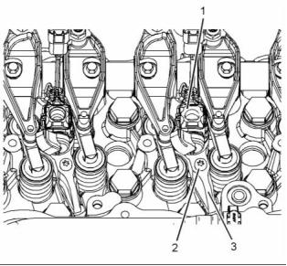
i04640270
Electronic Unit Injector - Install
(1606A and 1606D Engines)
g03174696
Illustration 26
2. Place an identification mark on electronic unit
injector (1) for installation purposes. Each
electronic unit injector must be reinstalled in the
original location in the cylinder head.
Installation Procedure
3. Use Tooling (A) to loosen fully Torx bolt (2). As
Torx bolt (2) is loosened, the electronic unit injector
will self extract from the cylinder head.
Table 5
Required Tools
Tool
D
Part Number
GE50028
Part Description
Vacuum Pump
Qty
1
4. Remove electronic unit injector (1) and clamp
assembly (3) from the cylinder head.
GE50046
Fluid Sampling Bottle
1
Note: Always handle electronic unit injector with care.
Tube
7.9 mm (0.31 inch) OD
GE50030
-
1
1
E
Large Bore Brush
NOTICE
Keep all parts clean from contaminants.
Contaminants may cause rapid wear and shortened
component life.
1. Use Tooling (E) to clean the carbon deposit from
the inside of the electronic unit injector sleeve.
2. Use Tooling (D) to remove the fuel and oil from
the cylinder. Evacuate as much fuel and oil as
possible from the cylinder before installing the
electronic unit injector. Several evacuations may
be necessary.
g03174716
Illustration 27
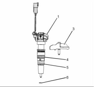
5. Remove clamp assembly (3) from electronic unit
injector (1).
This document is printed from SPI². Not for RESALE
![]()
![]()
![]()
![]()
![]()
20
KENR8773
Disassembly and Assembly Section
g03174796
g03174696
Illustration 28
Illustration 30
3. Ensure that the seat Area (X) of electronic unit
injector (1) is clean and free from carbon.
6. Position clamp assembly (3) on to electronic unit
injector (1). Ensure that the clamp assembly is
correctly located into the electronic unit injector
in Position (Y).
4. Install a new O-ring seal (4) and a new O-ring seal
(5) onto the electronic unit injector.
7. Install electronic unit injector (2) into the original
5. Install a new sealing washer (6) onto electronic
location in the cylinder head.
unit injector (1).
8. Use Tooling (A) in order to tighten Torx bolt (2)
Note: Ensure that the nozzle for the electronic unit
injector is not damaged in any way as a new sealing
washer is installed.
hand tight.
9. Tighten Torx bolt (4) to a torque of 41 N·m (30 lb ft).
10. If necessary, repear Step 1 through Step 9 in
order to install the remaining electronic unit
injectors (2).
11. Turn the fuel supply to the ON position.
12. Install the unit injector actuation oil manifold.
Refer to Disassembly and Assembly, “Unit Injector
Actuation Oil Manifold - Remove and Install”.
13. Remove the air from the fuel system. Refer to
Systems Operation, Testing and Adjusting, “Fuel
System - Prime”.
g03174836
Illustration 29
This document is printed from SPI². Not for RESALE
![]()
![]()
![]()
![]()
KENR8773
21
Disassembly and Assembly Section
i04640271
Electronic Unit Injector Sleeve
- Remove
(1606A and 1606D Engines)
Removal Procedure
Table 6
Required Tools
Tool
Part Number
Part Description
Qty
(1" x 8 TPI UNC) Thread
Tap
1
A
27610362
Guide
1
1
1
Adapter
B
C
27610311
-
Slide Hammer Puller
(5/8"X 18 TPI UNF) by 4"
Long Stud
1
Start By:
a. Remove the electronic unit injectors. Refer to
Disassembly and Assembly, “Electronic Unit
Injector - Remove”.
g03175098
Illustration 31
2. Plugging of an electronic unit injector sleeve (1)
will be necessary in order to stop debris entering
the cylinder bore. Plugging of the electronic unit
injector sleeve will only be required if the cylinder
head in still installed to the engine
NOTICE
Keep all parts clean from contaminants.
Contaminants may cause rapid wear and shortened
component life.
3. Apply lubricant to the thread tap of Tooling (A).
Use the guide and the threaded tap of Tooling (A)
in order to cut a thread in electronic unit injector
sleeve (1). Screw in the thread tap of Tooling (A)
into the electronic unit injector sleeve by 19 mm
(0.75 inch).
1. Drain the coolant from the engine. Refer to
Operation and Maintenance Manual, “Cooling
System Coolant - Change”.
4. Remove both the guide and the thread tap of
Tooling (A) from the electronic unit injector sleeve.
This document is printed from SPI². Not for RESALE
![]()
![]()
![]()
![]()
免費熱線
400-100-8969???15088860848
400-100-8969???15088860848
機組銷售
0574-26871589? 15267810868
0574-26871589? 15267810868
配件銷售
0574-26886646? 15706865167
0574-26886646? 15706865167
維修熱線
0574-26871569 18658287286
0574-26871569 18658287286
手機端

微信公眾號