 English
 Espaol
 Franais
 阿拉伯
阿拉伯 中文(簡)
中文(簡) Deutsch
 Italiano
 Português
 日本
日本 韓國
韓國 български
 hrvatski
 esky
esky Dansk
Dansk Nederlands
 suomi
suomi Ελληνικ
 印度
印度 norsk
norsk Polski
 Roman
Roman русский
 Svenska
 珀金斯Perkins1600發動機故障維修排除資料手冊,珀金斯Perkins1600發動機故障維修排除資料手冊技術支持中心,珀金斯Perkins1600發動機故障維修排除資料手冊代理商,珀金斯Perkins1600發動機故障維修排除資料手冊銷售服務中心,珀金斯Perkins1600發動機故障維修排除資料手冊價格規格資料查詢,寧波日昕動力科技有限公司

珀金斯Perkins1600發動機故障維修排除資料手冊
詳細描述
Troubleshooting
1600 Series Industrial Engine
Table of Contents
Oil Pressure Is Low..................... .................... 89
Power Is IntermittentlyLow or Power Cutout Is
Intermittent.......................... .......................... 93
Valve Lash Is Excessive................. ................ 96
TroubleshootingSection
Electronic Troubleshooting
Troubleshootingwith a Diagnostic Code
Diagnostic Trouble Codes ............... ............... 97
Diagnostic Code Cross Reference........ ....... 100
Welding Precaution ..................... ..................... 5
System Overview....................... ....................... 5
Glossary .......................................................... 10
Electronic Service Tools ................. ................ 13
Replacing the ECM..................... .................... 19
Self-Diagnostics....................... ....................... 19
Sensors and Electrical Connectors ........ ........ 20
Engine Wiring Information............... ............... 27
ECM Harness Connector Terminals........ ....... 30
Diagnostic Functional Tests
CAN Data Link - Test .................. .................. 104
Data Link - Test....................... ...................... 108
ECM Memory - Test................... ....................112
Electrical Connector - Inspect............ ............115
Electrical Power Supply - Test (Electronic
Control Module)..................... ......................118
Electrical Power Supply - Test (Injector Driver
Module)............................ ........................... 122
Injection Actuation Pressure - Test........ ....... 127
Injection Actuation Pressure Control Valve -
Test ............................... .............................. 131
Injection Actuation Pressure Sensor - Test.. . 134
Injector Solenoid - Test................. ................ 139
Sensor Supply - Test................... .................. 144
Sensor Signal (Analog, Active) - Test (Engine Oil
Pressure Sensor).................... .................... 147
Sensor Signal (Analog, Active) - Test (Manifold
Absolute Pressure Sensor)............. ............ 151
Sensor Signal (Analog, Active) - Test (Engine
Fuel Pressure Sensor)................ ................ 155
Sensor Signal (Analog, Active) - Test (Exhaust
Back Pressure Sensor)................ ............... 159
Sensor Signal (Analog, Passive) - Test (Engine
Oil Temperature)..................... .................... 163
Sensor Signal (Analog, Passive) - Test (Engine
Coolant Temperature Sensor)........... .......... 166
Sensor Signal (Analog, Passive) - Test (Intake
Manifold Air Temperature Sensor)....... ....... 170
Speed/Timing - Test (Camshaft Position
Programming Parameters
Programming Parameters ............... ............... 31
Flash Programming.................... .................... 31
Symptom Troubleshooting
Alternator Is Noisy ..................... ..................... 32
Alternator Problem..................... ..................... 34
Battery Problem....................... ....................... 35
Coolant Contains Oil.................... ................... 36
Coolant Level Is Low ................... ................... 36
Coolant Temperature Is High............. ............. 37
Cylinder Is Noisy....................... ...................... 40
ECM Does Not Communicate with Other
Modules............................ ............................ 43
Electronic Service Tool Does Not
Communicate........................ ........................ 47
Engine Cranks but Does Not Start......... ......... 49
Engine Does Not Crank................. ................. 54
Engine Has Early Wear ................. ................. 57
Engine Has Mechanical Noise (Knock)..... ..... 59
Engine Misfires, Runs Rough or Is Unstable. . 61
Engine Overspeeds.................... .................... 63
Engine Shutdown Occurs Intermittently..... .... 64
Engine Top Speed Is Not Obtained........ ........ 65
Engine Vibration Is Excessive............ ............ 67
Exhaust Back Pressure Problem.......... .......... 70
Exhaust Has Excessive Black Smoke...... ...... 71
Exhaust Has Excessive White Smoke ............ 73
Fuel Consumption Is Excessive ........... .......... 76
Fuel Contains Water.................... ................... 79
Fuel Pressure Problem.................. ................. 79
Injection Actuation Pressure Problem ...... ...... 80
Oil Consumption Is Excessive............ ............ 84
Oil Contains Coolant.................... ................... 85
Oil Contains Fuel...................... ...................... 87
Sensor)............................ ........................... 174
Speed/Timing - Test (Crankshaft Position
Sensor)............................ ........................... 177
Starting Aid - Test (Inlet Air Heater)....... ....... 181
Switch Circuits - Test (Engine Coolant Level
Switch)............................ ............................ 186
Valve Position - Test (Exhaust Gas Recirculation
Valve)............................. ............................. 189
Water in Fuel - Test.................... ................... 195
Index Section
This document has been printed from SPI2. NOT FOR RESALE.
![]()
4
KENR8774
Table of Contents
Index............................... .............................. 199
This document has been printed from SPI2. NOT FOR RESALE.
![]()
KENR8774
5
Electronic Troubleshooting
TroubleshootingSection
Electronic Troubleshooting
i05340059
Welding Precaution
Correct welding procedures are necessary in order to
avoid damage to the following components:
• Electronic Control Module (ECM) on the engine
• Sensors
• Associated components
Illustration 1
g01143634
Components for the driven equipment should also be
considered. When possible, remove the component
that requires welding. When welding on an engine
that is equipped with an ECM and removal of the
component is not possible, the following procedure
must be followed. This procedure minimizes the risk
to the electronic components.
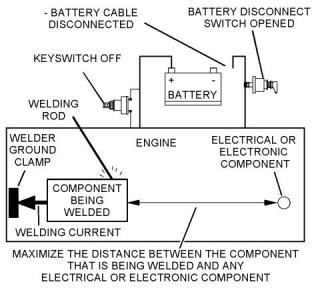
Service welding guide (typical diagram)
5. When possible, connect the ground clamp for the
welding equipment directly to the engine
component that will be welded. Place the clamp as
close as possible to the weld. Close positioning
reduces the risk of welding current damage to the
engine bearings, to the electrical components, and
to other components.
1. Stop the engine. Remove the electrical power from
the ECM.
2. Ensure that the fuel supply to the engine is turned
off.
6. Protect the wiring harnesses from welding debris
and/or from welding spatter.
3. Disconnect the negative battery cable from the
battery. If a battery disconnect switch is installed,
open the switch.
7. Use standard welding procedures to weld the
materials together.
4. Disconnect all electronic components from the
wiring harnesses. Include the following
components:
i05513196
System Overview
• Electronic components for the driven equipment
The engine has an electronic control system. The
system controls the engine.
• ECM
• Sensors
The control system consists of the following
components:
• Electronically controlled valves
• Relays
• Electronic Control Module (ECM)
• Software (flash file)
• Wiring
NOTICE
Do not use electrical components (ECM or ECM sen-
sors) or electronic component grounding points for
grounding the welder.
• Sensors
• Actuators
The following information provides a general
description of the control system. Refer to Systems
Operation, Testing, and Adjusting for detailed
information about the control system.
This document has been printed from SPI2. NOT FOR RESALE.
![]()
![]()
![]()
![]()
![]()
6
KENR8774
Electronic Troubleshooting
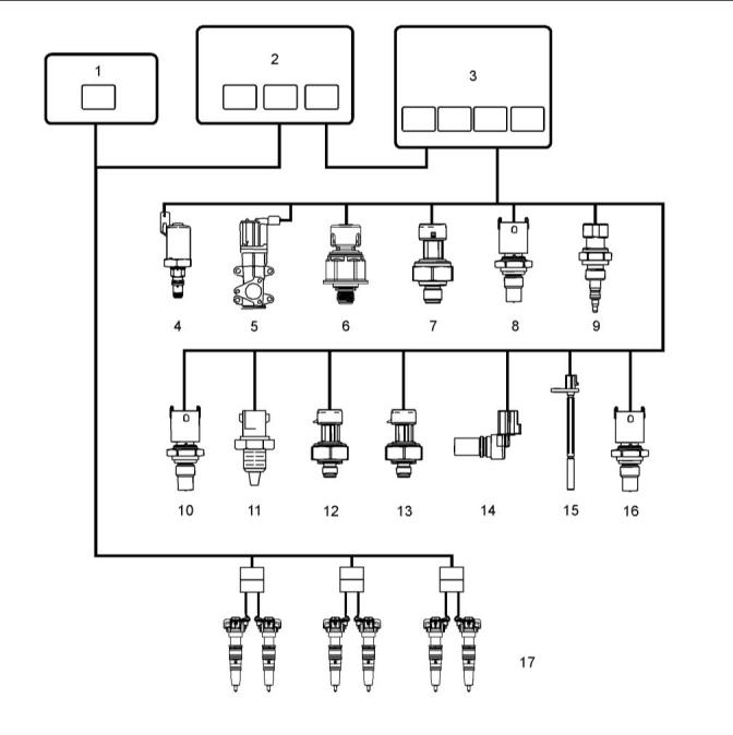
Electronic Control Circuit Diagram
Illustration 2
g03383024
(1) Exhaust Gas Recirculation (EGR) control
module
(2) Injector drive module (IDM)
(3) Electronic Control Module (ECM)
(including internal barometric pressure
sensor)
(5) Exhaust Gas Recirculation (EGR) valve
(11) Inlet Air Temperature sensor
(6) Injection Control Pressure (ICP) sensor
(7) Engine Fuel Pressure (EFP) sensor
(8) Engine Coolant Temperature (ECT)
sensor
(9) Manifold Air Pressure (MAP) sensor
(10) Manifold Air Temperature (MAT) sensor
(12) Exhaust Back Pressure (EBP) sensor
(13) Engine Oil Pressure (EOP) sensor
(14) Camshaft Position (CMP) sensor
(15) Crankshaft Position (CKP) sensor
(16) Engine Oil Temperature (EOT) sensor
(17) Fuel injectors
(4) Injector Pressure Regulator (IPR)
This document has been printed from SPI2. NOT FOR RESALE.
![]()
![]()
KENR8774
7
Electronic Troubleshooting
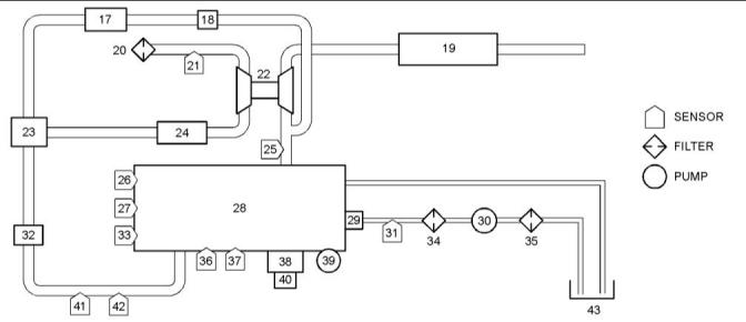
Block Diagram
Illustration 3
g02276814
Block diagram for the 1600 engine
(17) EGR cooler
(18) EGR valve
(19) Muffler
(20) Air cleaner
(21) Inlet Air Temperature(IAT) sensor
(22) Turbocharger
(23) EGR mixer
(24) Charge Air Cooler (CAC)
(25) Exhaust Back Pressure (EBP) sensor
(26) Engine Coolant Temperature (ECT)
sensor
(27) Crankshaft Position (CKP) sensor
(28) Engine
(35) Fuel strainer
(36) Injection Control Pressure (ICP) sensor
(37) Engine Oil Pressure (EOP) sensor
(38) Electronic control module (ECM)
(39) High-pressureoil pump
(40) Injector Drive Module (IDM)
(41) Manifold Air Temperature (MAT) sensor
(42) Manifold Air Pressure (MAP) sensor
(43) Fuel tank
(29) Injectors
(30) Low-pressure fuel pump
(31) Engine Fuel Pressure (EFP) sensor
(32) Inlet Air Heater (IAH)
(33) Camshaft Position (CMP) sensor
(34) Fuel filter
The Electronic Control Module (ECM) monitors and
controls engine performance to ensure maximum
performance and adherence to emissions standards.
The ECM has four primary functions:
values to determine the correct operating strategy for
all engine operations. Diagnostic Trouble Codes
(DTCs) are generated by the microprocessor, if inputs
or conditions do not comply with expected values.
• Provides reference voltage
• Conditions input signals
Diagnostic strategies are also programmed into the
ECM. Some strategies monitor inputs continuously
and command the necessary outputs to achieve the
correct performance of the engine.
• Processes and stores control strategies
• Controls actuators
Actuator control – The ECM controls the actuators
by applying a low-level signal (low side driver) or a
high-level signal (high side driver). When switched
on, the drivers complete a ground or power circuit to
an actuator.
Reference Voltage – The ECM supplies a 5 VDC
signal to input sensors in the electronic control
system. By comparing the 5 VDC signal sent to the
sensors with the respective returned signals, the
ECM determines pressures, positions, and other
variables important to engine functions.
Actuators are controlled in three ways, determined by
the type of actuator:
Signal Conditioner – The signal conditioner in the
internal microprocessor converts analog signals to
digital signals, squares up sine wave signals, or
amplifies low intensity signals to a level that the ECM
microprocessor can process.
• A duty cycle (percent time on/off)
• A controlled pulse-width
• Switched on or off
Microprocessor – The ECM microprocessor stores
operating instructions (control strategies) and value
tables (calibration parameters). The ECM compares
stored instructions and values with conditioned input
This document has been printed from SPI2. NOT FOR RESALE.
![]()
![]()
8
KENR8774
Electronic Troubleshooting
Exhaust Gas Recirculation(EGR) Control
Valve
The ECM sends information (fuel volume, engine oil
temperature, and injection control pressure) through
the CAN 2 datalink to the IDM. The IDM uses this
information to calculate the injection cycle.
The EGR valve controls the flow of exhaust gases
into the inlet and EGR mixer duct.
Injector Power Source
The EGR drive module controls the EGR actuator.
The IDM creates a constant 48 VDC supply to all
injectors by making and breaking a 12 VDC source
across a coil in the IDM. The 48 VDC created by the
collapsed field is stored in capacitors until used by the
injectors.
The EGR drive module receives the desired EGR
actuator position from the ECM across the CAN 2
datalink to activate the valve for exhaust gas
recirculation. The EGR drive module provides
feedback to the ECM on the valve position.
The IDM controls when the injector is turned on and
how long the injector is active. The IDM first
The EGR drive module constantly monitors the EGR
actuator. When an EGR control error is detected, the
EGR drive module sends a message to the ECM and
a DTC is set.
energizes the OPEN coil, then the CLOSE coil. The
low side driver supplies a return circuit to the IDM for
each injector coil (open and close). The high side
driver controls the power supply to the injector. During
each injection event, the low and high side drivers are
switched on and off for each coil.
Injection Pressure Regulator (IPR)
The IPR valve controls pressure in the Injection
Control Pressure (ICP) system. The IPR valve is a
variable position valve controlled by the ECM. This
regulated pressure actuates the fuel injectors. The
valve position is controlled by switching the ground
circuit in the ECM. The voltage source is supplied by
the ignition switch.
IDM and Injector Diagnostics
The IDM determines if an injector is drawing enough
current. The IDM sends a fault to the ECM, indicating
potential problems in the wiring harness or injector,
and the ECM will set a DTC. The IDM also does self-
diagnostic checks and sets a DTC to indicate failure
of the IDM.
Inlet Air Heater (IAH)
On-demand tests can be done using the Electronic
Service Tool (EST). The ESTsends a request to the
ECM and the ECM sends a request to the IDM to do a
test. Some tests generate a DTC when a problem
exists. Other tests require the technician to evaluate
parameters, if a problem exists.
The IAH system warms the incoming air supply prior
to cranking to aid cold engine starting and reduce
white smoke during warm-up.
The ECM is programmed to energize the IAH
elements through the IAH relays while monitoring
certain programmed conditions for engine coolant
temperature, engine oil temperature, and
atmospheric pressure.
Engine Sensors
Temperature Sensors
Injection Drive Module (IDM)
A thermistor sensor changes electrical resistance
with changes in temperature. Resistance in the
thermistor decreases as temperature increases, and
increases as temperature decreases. Thermistors
work with a resistor that limits current in the ECM to
form a voltage signal matched with a temperature
value.
The IDM has three functions:
• Electronic distributor for injectors
• Power source for injectors
• IDM and injector diagnostics
The top half of the voltage divider is the current
limiting resistor inside the ECM. A thermistor sensor
has two electrical connectors, signal return and
ground. The output of a thermistor sensor is a
nonlinear analog signal.
The IDM distributes current to the injectors. The IDM
controls fueling to the engine by sending high voltage
pulses to the OPEN and CLOSE coils of the injector.
The IDM uses information from the ECM to determine
the timing and quantity of fuel for each injector.
Engine Coolant Temperature (ECT)
The ECM uses CKP sensor and CMP sensor input
signals to calculate engine speed and position. The
ECM conditions both input signals and supplies the
IDM with the speed/timing sensor output signals. The
IDM uses these signals to determine the correct
sequence for injector firing.
The ECM monitors the ECTsignal and uses this
information for the instrument panel temperature
gauge, coolant compensation, Engine Warning
Protection System (EWPS), and inlet air heater
operation. The ECT is a backup, if the engine oil
temperature is out-of-range. The ECTsensor is
installed in the water supply housing , right of the flat
idler pulley assembly.
This document has been printed from SPI2. NOT FOR RESALE.
![]()
KENR8774
9
Electronic Troubleshooting
Engine Oil Temperature (EOT)
Exhaust Back Pressure (EBP)
The ECM monitors the EOTsignal to control fuel
quantity and timing when operating the engine. The
EOTsignal allows the ECM and IDM to compensate
for differences in oil viscosity for temperature
changes. This compensation ensures that power and
torque are available for all operating conditions. The
EOTsensor is installed in the rear of the front cover,
left of the high-pressure oil pump assembly.
The EBP sensor measures exhaust back pressure so
that the ECM can control the EGR system. The
sensor provides feedback to the ECM for closed loop
control of the Turbocharger. The EBP sensor is
installed in a bracket mounted on the water supply
housing.
Engine Fuel Pressure (EFP)
Intake Air Temperature (IAT)
The ECM uses the EFP sensor signal to monitor
engine fuel pressure and give an indication when the
fuel filter needs to be changed. The EFP sensor is
installed in the rear of the fuel filter assembly
(crankcase side).
The ECM monitors the IATsignal to control timing and
fuel rate during cold starts. The IATsensor is mounted
on the air filter housing.
Manifold Air Temperature (MAT)
Micro Strain Gauge Sensors
The ECM monitors the MATsignal for EGR operation.
The MATsensor is installed in the intake manifold.
A micro strain gauge sensor measures pressure.
Pressure to be measured exerts force on a pressure
vessel that stretches and compresses to change
resistance of strain gauges bonded to the surface of
the pressure vessel. Internal sensor electronics
convert the changes in resistance to a ratio metric
voltage output.
Variable capacitance sensor
Variable capacitance sensors measure pressure. The
pressure measured is applied to a ceramic material.
The pressure forces the ceramic material closer to a
thin metal disk. This action changes the capacitance
of the sensor.
The sensor is connected to the ECM by three wires:
• 5 VDC supply
The sensor is connected to the ECM by three wires:
• 5 VDC supply
• Signal return
• Signal ground
• Signal return
The sensor receives the 5 VDC supply and returns an
analog signal voltage to the ECM. The ECM
compares the voltage with pre-programmed values to
determine pressure.
• Signal ground
The sensor receives the 5 VDC and returns an
analog signal voltage to the ECM. The ECM
compares the voltage with pre-programmed values to
determine pressure.
Injection Control Pressure (ICP)
The ECM monitors the ICP signal to determine the
injection control pressure for engine operation. The
ICP signal is used to control the IPR valve. The ICP
sensor provides feedback to the ECM for Closed
Loop ICP control. The ICP sensor is under the valve
cover, forward of the No. 6 fuel injector in the high-
pressure oil rail.
Barometric Absolute Pressure (BAP)
The ECM monitors the BAP signal to determine
altitude, adjust timing, fuel quantity, and inlet air
heater operation.
Intake Manifold Air Pressure (MAP)
Magnetic Pickup Sensors
The ECM monitors the MAP signal to determine
intake manifold pressure (boost). This information is
used to control fuel rate and injection timing. The
MAP sensor is installed left of the MATsensor in the
intake manifold.
A magnetic pickup sensor generates an alternating
frequency that indicates speed. Magnetic pickups
have a two wire connection for signal and ground.
This sensor has a permanent magnetic core
surrounded by a wire coil. The signal frequency is
generated by the rotation of gear teeth that disturb the
magnetic field.
Engine Oil Pressure (EOP)
The ECM monitors the EOP signal, and uses this
information for the instrument panel pressure gauge
and EWPS. The EOP sensor is installed in the left
side of the crankcase below and left of the fuel filter
housing.
This document has been printed from SPI2. NOT FOR RESALE.
![]()
10
KENR8774
Electronic Troubleshooting
Crankshaft Position (CKP) sensor
Event Codes
Event Codes are used to indicate that the ECM has
detected an abnormal engine operating condition.
The ECM will log the occurrence of the event code.
An event code does not indicate an electrical
malfunction or an electronic malfunction. For
example, if the temperature of the coolant in the
engine is higher than the permitted limit, then the
ECM will detect the condition. The ECM will then log
an event code for the condition.
The CKP sensor provides the ECM with a signal that
indicates crankshaft speed and position. As the
crankshaft turns, the CKP sensor detects a 60 tooth
timing disk on the crankshaft. Teeth 59 and 60 are
missing. By comparing the crankshaft signal with the
camshaft signal, the ECM calculates engine rpm and
timing requirements. The CKP sensor is installed in
the top left side of the flywheel housing.
Camshaft Position (CMP) sensor
Engine Warning Protection System
(EWPS)
The CMP sensor provides the ECM with a signal that
indicates camshaft position. As the cam rotates, the
sensor identifies the position of the cam by locating a
peg on the cam. The CMP is installed in the front
cover, above and to the left of the water pump pulley.
The EWPS safeguards the engine from undesirable
operating conditions to prevent engine damage and
to prolong engine life. The ECM will illuminate the red
ENGINE lamp when the ECM detects:
Switches
• High coolant temperature
• Low oil pressure
Switch sensors indicate position, level, or status.
Switch sensors operate open or closed, allowing or
preventing the flow of current. A switch sensor can be
a voltage input switch or a grounding switch. A
voltage input switch supplies the ECM with a voltage
when closed. A grounding switch will ground the
circuit when closed, causing a zero voltage signal.
Grounding switches are usually installed in series
with a current limiting resistor.
• Low coolant level
When the protection feature is enabled and a critical
engine condition occurs, the on-board electronics will
shut down the engine. An event logging feature will
record the event in engine hours. After the engine has
shutdown, and the critical condition remains, the
engine can be started for a 30 second run time.
Water In Fuel (WIF)
i05510289
A Water In Fuel (WIF) switch in the element cavity of
the fuel filter housing detects water. When enough
water accumulates in the element cavity, the WIF
sensor signal changes to the Electronic Control
Module (ECM). The ECM sends a message to
illuminate the amber water and fuel lamp, alerting the
operator. The WIF is installed in the base of the fuel
filter housing.
Glossary
Actuator – A device that performs work in response
to an input signal.
Aeration – The entrapment of gas (air or combustion
gas) in the coolant, lubricant, or fuel.
Diagnostic Trouble Codes (DTC)
After cooler (Charge Air Cooler) – A heat
exchanger mounted in the charge air path between
the turbocharger and engine intake manifold. The
after cooler reduces the charge air temperature by
transferring heat from the charge air to a cooling
medium (usually air).
Diagnostic Codes
When the ECM detects an electronic system fault, the
ECM generates a diagnostic code. Also, the ECM
logs the diagnostic code in order to indicate the time
of the occurrence. The ECM also logs the number of
occurrences of the fault. Diagnostic codes are
provided in order to indicate that the ECM has
detected an electrical fault or an electronic fault with
the engine control system. In some cases, the engine
performance can be affected when the condition that
is causing the code exists.
Air Management System (AMS) – The AMS
controls and directs air through the intake and
exhaust which affects engine performance and
controls emissions.
Alternating Current (AC) – An electric current that
reverses direction at regularly recurring intervals.
If the operator indicates that a performance issue
occurs, the diagnostic code may indicate the cause of
the issue. Use the electronic service tool to access
the diagnostic codes. Any fault should then be
corrected.
Ambient temperature – The environmental air
temperature in which a unit is operating. In general,
the temperature is measured in the shade (no solar
radiation) and represents the air temperature for other
engine cooling performance measurement purposes.
Air entering the radiator may or may not be the same
ambient due to possible heating from other sources
or recirculation.
This document has been printed from SPI2. NOT FOR RESALE.
![]()
KENR8774
11
Electronic Troubleshooting
Ampere (amp) – The standard unit for measuring the
strength of an electrical current. The flow rate of a
charge in a conductor or conducting medium of 1
coulomb per second.
Crankshaft (CKP) sensor – The CKP sensor is a
magnetic pickup sensor that indicates crankshaft
speed and position.
Current – The flow of electrons passing through a
Analog – A continuously variable voltage.
conductor. Measured in amperes.
American Trucking Association (ATA) Data link –
A serial data link specified by the American Trucking
Association and the SAE.
Damper – A device that reduces the amplitude of
torsional vibration.
Diagnostic Trouble Code (DTC) – Formerly called a
Fault Code. A DTC is a three digit numeric code used
for troubleshooting.
Barometric Absolute Pressure (BAP) sensor – A
variable capacitance sensor which, when supplied
with a 5 V reference signal from the ECM, produces a
linear analog voltage signal indicating atmospheric
pressure.
Direct Current (DC) – An electric current flowing in
one direction only and substantially constant in value.
Boost pressure – The pressure of the charge air
leaving the turbocharger or inlet manifold pressure
that is greater than atmospheric pressure. Obtained
by turbocharging.
Disable – A computer decision that deactivates a
system and prevents operation of the system.
Displacement – The stroke of the piston multiplied
by the area of the cylinder bore multiplied by the
number of cylinders in the engine.
Bottom Dead Center (BDC) – The lowest position of
the piston during the stroke.
Electronic Control Module (ECM) – The Electronic
Control Module is an electronic microprocessor that
monitors and controls engine performance, exhaust
emissions, and engine system performance. The
ECM provides diagnostic information for engine
systems and can be programmed at different levels
for engine protection, warning, and shutdown.
Calibration – The data values used by the strategy to
solve equations and make decisions. Calibration
values are stored in ROM and put into the processor
during programming to allow the engine to operate
within certain parameters.
Camshaft Position (CMP) sensor – The CMP
sensor is a magnetic pickup sensor which indicates
engine position. Speed is indicated by the number of
vanes counted per revolution of the camshaft.
Camshaft position is indicated by a single position
peg that indicates Cylinder Number 1.
Engine Control Module (ECM) power relay – An
ECM controlled relay that supplies power to the ECM.
Electronic Service Tool (EST) – A computer
diagnostic and programming tool for the ECM. The
hardware is typically a laptop computer or notebook
computer.
Charge air – Dense, pressurized, heated air
discharged from the turbocharger.
Engine Coolant Temperature (ECT) sensor – A
thermistor sensor that senses engine coolant
temperature.
Closed crankcase – Crankcase ventilation system
that recycles crankcase gases through a breather,
then back to the clean air intake.
Engine Fuel Pressure (EFP) sensor – A variable
Closed loop operation – A system that uses a
sensor to provide feedback to the ECM. The ECM
uses the sensor to continuously monitor variables
and make adjustments in order to match engine
requirements.
capacitance sensor that senses fuel pressure.
Engine Family Rating Code (EFRC) – A readable
code in the calibration list of the EST that identifies
engine horsepower and emission calibrations.
Engine OFF tests – Tests that are done with the
ignition key ON and the engine OFF.
Continuous Monitor Test – An ECM function that
continuously monitors the inputs and outputs to
ensure that readings are within set limits.
Engine RUNNING tests – Tests done with the engine
running.
Controller Area Network (CAN) – A J1939 high
speed communication link. CAN 1 is a public data link
between other modules and the ECM. CAN 2 is a
private link between the ECM and IDM.
Engine Oil Pressure (EOP) sensor – A variable
capacitance sensor that senses engine oil pressure.
Engine Oil Temperature (EOT) sensor – A
thermistor sensor that senses engine oil temperature.
Coolant – A fluid used to transport heat from one
point to another.
Exhaust Gas Recirculation (EGR) – The Exhaust
Gas Recirculation is a system that recycles a
controlled portion of exhaust gas back into the
combustion chamber to reduce Nitrogen Oxide
exhaust emissions.
Crankcase – The housing that encloses the
crankshaft, connecting rods, and allied parts.
Crankcase breather – A vent for the crankcase to
release excess interior air pressure.
Crankcase pressure – The force of air inside the
crankcase against the crankcase housing.
Exhaust Gas Recirculation (EGR) drive module –
The EGR drive module controls the position of the
EGR valve.
This document has been printed from SPI2. NOT FOR RESALE.
![]()
12
KENR8774
Electronic Troubleshooting
Exhaust Gas Recirculation (EGR) cooler – The
exhaust gas is cooled in the EGR cooler and flows
through the EGR control valve to the EGR mixer duct.
Injection Control Pressure (ICP) sensor – A
variable capacitance sensor that senses injection
control pressure.
Exhaust Gas Recirculation (EGR) valve – The EGR
valve, when open, will mix exhaust gas with filtered
intake air which flows into the intake manifold. The
EGR valve, when closed, only allows filtered air to
flow into the intake manifold.
Injector Drive Module (IDM) power relay – An IDM
controlled relay that supplies power to the IDM.
Intake Air Temperature (IAT) sensor – A thermistor
sensor that senses intake air temperature.
Intake manifold – A plenum through which the air
mixture flows from the charged air cooler piping to the
intake passages of the cylinder head.
Exhaust manifold – Exhaust gases flow through the
exhaust manifold to the turbocharger exhaust inlet
and are directed to the EGR cooler or out the exhaust
system.
Intake Manifold Air Pressure Sensor (MAP) – The
Intake Manifold Pressure Sensor measures the
pressure in the intake manifold. The pressure in the
intake manifold may be different to the pressure
outside the engine (atmospheric pressure). The
difference in pressure may be caused by an increase
in air pressure by a turbocharger.
Fault detection and management – An alternate
control strategy that reduces adverse effects that can
be caused by a system failure. If a sensor fails, the
ECM substitutes a good sensor signal or assumed
sensor value.
Filter restriction – A blockage, usually from
contaminants, that prevents the flow of fluid through a
filter.
Intake Manifold Air Temperature Sensor (MAT) – A
thermistor style sensor housed in the intake manifold
used to indicate air temperature after passing through
the charge air cooler.
Flash File – This file is software that is inside the
ECM. The file contains all the instructions (software)
for the ECM and the file contains the performance
maps for a specific engine. The file may be
J1939 CAN Data Links – These data links are SAE
standard diagnostic communications data links that
are used to communicate between the ECM and
other electronic devices.
reprogrammed through flash programming.
Flash Programming – Flash programming is the
method of programming or updating an ECM with an
electronic service tool over the data link instead of
replacing components.
Logged Diagnostic Codes – Logged diagnostic
codes are codes which are stored in the memory.
These codes are an indicator of possible causes for
intermittent problems. Refer to the term “Diagnostic
Trouble Codes” for more information.
Fuel inlet restriction – A blockage, usually from
contaminants, that prevents the flow of fluid through
the fuel inlet line.
Lubricity – Lubricity is the ability of a substance to
reduce friction between solid surfaces in relative
motion under loaded conditions.
Fuel pressure – The force that the fuel exerts on the
fuel system as it is pumped through the fuel system.
Microprocessor – An integrated circuit in a
Fuel strainer – A pre-filter in the fuel system that
keeps larger contaminants from entering the fuel
system.
microcomputer that controls information flow.
Nitrogen Oxides (NOx) – Nitrogen oxides form by a
reaction between nitrogen and oxygen at high
temperatures and pressures in the combustion
chamber.
Hall effect – The development of a transverse
electric potential gradient in a current-carrying
conductor or semiconductor when a magnetic field is
applied.
Normally closed – Refers to a switch that remains
closed when no control force is acting on it.
Hall effect sensor – Generates a digital on or off
signal that indicates speed or position.
Normally open – Refers to a switch that remains
open when no control force is acting on it.
Harness – The harness is the bundle of wiring (loom)
that connects all components of the electronic
system.
Ohm (Ω) – The unit of resistance. 1 ohm is the value
of resistance through which a potential of 1 V will
maintain a current of 1 ampere.
Hertz (Hz) – Hertz is the measure of electrical
frequency in cycles per second.
On-demand test – A self test that the technician
initiates using the EST. It is run from a program in the
processor.
Injection Pressure Regulator (IPR) – A PulseWidth
Modulated (PWM) regulator valve, controlled by the
ECM, that regulates injection control pressure.
Open Circuit – An open circuit is a condition that is
caused by an open switch, or by an electrical wire or
a connection that is broken. When this condition
exists, the signal or the supply voltage can no longer
reach the intended destination.
Injection Control Pressure (ICP) – High lube oil
pressure generated by a high-pressure pump/
pressure regulator used to hydraulically actuate the
fuel injectors.
Output Circuit Check (OCC) – An On-demand test
done during an Engine OFF self test to check the
continuity of selected actuators.
This document has been printed from SPI2. NOT FOR RESALE.
![]()
KENR8774
13
Electronic Troubleshooting
Supply Voltage – The supply voltage is a continuous
voltage that is supplied to a component. The power
may be generated by the ECM or the power may be
battery voltage that is supplied by the engine wiring.
Output State Check (OSC) – An On-demand test
that forces the processor to activate actuators (High
or Low) for additional diagnostics.
Parameter – A parameter is a value or a limit that is
programmable. A parameter helps determine specific
characteristics or behaviors of the engine.
Switch sensors – Switch sensors indicate position.
They operate open or closed, allowing or preventing
the flow of current. A switch sensor can be a voltage
input switch or a grounding switch. A voltage input
switch supplies the ECM with a voltage when it is
closed. A grounding switch grounds the circuit closed,
causing a zero voltage signal. Grounding switches
are usually installed in series with a current limiting
resistor.
Particulate matter – Particulate matter includes
mostly burned particles of fuel and engine oil.
Potentiometer – A potentiometer is a variable
voltage divider that senses the position of a
mechanical component. A reference voltage is
applied to one end of the potentiometer. Mechanical
rotary or linear motion moves the wiper along the
resistance material, changing voltage at each point
along the resistive material. Voltage is proportional to
the amount of mechanical movement.
Top Dead Center (TDC) – The highest position of the
piston during the stroke.
Torque – Torque is a measure of force producing
torsion and rotation around an axis. Torque is the
product of the force, usually measured in pounds, and
radius perpendicular to the axis of the force extending
to the point where the force is applied or where it
originates, usually measured in feet.
Power Cycling – Power cycling refers to the action of
cycling the keyswitch from any position to the OFF
position, and to the START/RUN position.
Pulse Width Modulation (PWM) – The time that an
actuator, such as an injector, remains energized.
Turbocharger – A turbine driven compressor
mounted to the exhaust manifold. The turbocharger
increases the pressure, temperature, and density of
intake air to charge air.
Random Access Memory (RAM) – Computer
memory that stores information. Information can be
written to and read from RAM. Input information
(current engine speed or temperature) can be stored
in RAM to be compared to values stored in Read
Only Memory (ROM). All memory in RAM is lost when
the ignition switch is turned off.
Valve cover gasket – A valve cover gasket that
contains the pass through electronic wiring harness
connectors for the ICP sensor, and six fuel injectors.
Variable capacitance sensor – A variable
capacitance sensor is a sensor that measures
pressure. The pressure measured is applied to a
ceramic material. The pressure forces the ceramic
material closer to a thin metal disk. This action
changes the capacitance of the sensor.
Read Only Memory (ROM) – Computer memory that
stores permanent information for calibration tables
and operating strategies. Permanently stored
information in ROM cannot be changed or lost by
turning the engine off or when ECM power is
interrupted.
Viscosity – The internal resistance to the flow of any
fluid.
Reference Voltage – Reference voltage is a
regulated voltage that is supplied by the ECM to a
sensor. The reference voltage is used by the sensor
to generate a signal voltage.
Volt (v) – A unit of electromotive force that will move
a current of 1 ampere through a resistance of 1 Ohm.
Voltage – Electrical potential expressed in volts.
Voltage drop – Reduction in applied voltage from the
current flowing through a circuit or portion of the
circuit current multiplied by resistance.
Relay – A relay is an electromechanical switch. A
flow of electricity in one circuit is used to control the
flow of electricity in another circuit. A small current or
voltage is applied to a relay in order to switch a much
larger current or voltage.
Wastegate – The wastegate is a device in a
turbocharged engine that controls the maximum
boost pressure that is provided to the inlet manifold.
Sensor – A sensor is a device that is used to detect
the current value of pressure or temperature, or
mechanical movement. The information that is
detected is converted into an electrical signal.
Water In Fuel (WIF) switch – The WIF switch detects
water in the fuel.
Short Circuit – A short circuit is a condition that has
an electrical circuit that is inadvertently connected to
an undesirable point. An example of a short circuit is
a wire which rubs against a vehicle frame and this
rubbing eventually wears off the wire insulation.
Electrical contact with the frame is made and results
in a short circuit.
i05513169
Electronic Service Tools
Perkins electronic service tools are designed to help
the service technician:
Signal – The signal is a voltage or a waveform that is
used in order to transmit information typically from a
sensor to the ECM.
This document has been printed from SPI2. NOT FOR RESALE.
![]()
14
KENR8774
Electronic Troubleshooting
• Retrieve diagnostic codes.
Connecting the Perkins 1306/1606
Diagnostic Software and the
• Diagnose electrical problems.
Communication Adapter 3 (CA3)
Service Tools
The following tools are used to diagnose electrical
faults.
Table 1
Required Service Tools
Part Number
27610376
Description
3-Way Adaptor Harness
27610398
Under Valve Cover (UVC) Sensor Breakout
Harness
27610374
27610375
27610393
27610377
Actuator Breakout Harness
500 Ohm Resistor Harness
Pressure Sensor Breakout Harness
Temperature Sensor Breakout Harness
27610378
Relay Breakout Harness
1306/1606 Perkins Diagnostic Tool
The Perkins Electronic Service Tool can display the
following information:
• Status of all pressure sensors and temperature
sensors
• Active diagnostic codes and logged diagnostic
codes
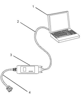
Illustration 4
g01121866
(1) Personal Computer (PC)
• Logged events
(2) Adapter Cable (Computer Serial Port)
(3) Communication Adapter 3 (CA3)
(4) Adapter Cable Assembly
The Electronic Service Tool can also be use, d to
perform diagnostic tests.
Note: Items (2), (3) and (4) are part of the CA3 kit.
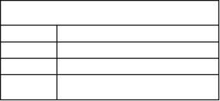
Table 2 lists the service tools that are required in
order to use the Electronic Service Tool.
Table 2
Use the following procedure in order to connect the
Perkins 1306/1606 Diagnostic Software and CA3.
Service Tools for the Use of the Electronic Service
Tool
1. Turn the keyswitch to the OFF position.
2. Connect cable (2) between the “COMPUTER”
end of communication adapter (3) and the USB l
port of PC (1).
Part Number
Description
Single Use Program License
Data Subscription for All Engines
-(1)
-
(1)
3. Connect cable (4) between the “DATA LINK” end
of communication adapter (3) and the service tool
connector.
Communication Adapter (Electronic Service Tool
to the ECM interface)
27610401
(1)
Refer to Perkins Engine Company Limited.
4. Place the keyswitch in the ON position.
Note: For more information on the Perkins 1306/
1606 Diagnostic Software and the PC requirements,
refer to the documentation that accompanies the
Perkins 1306/1606 Diagnostic Software.
This document has been printed from SPI2. NOT FOR RESALE.

![]()
![]()
![]()
KENR8774
15
Electronic Troubleshooting
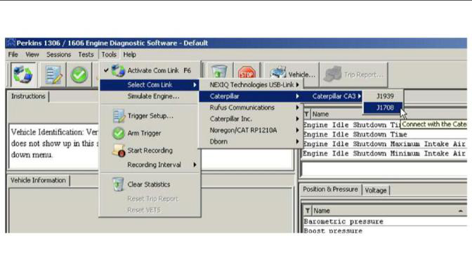
Illustration 5
g03384803
5. Select the correct data link. Refer to Illustration 5
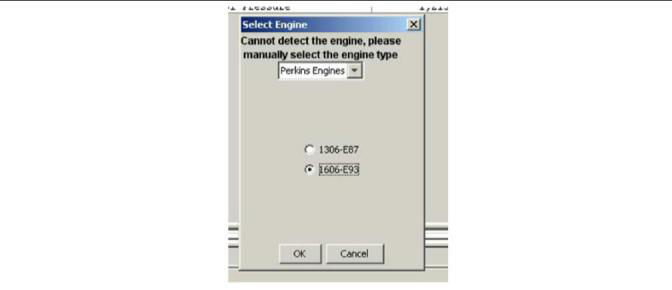
Illustration 6
g03384841
6. Select the correct engine type. Refer to Illustration
6 .
7. If the Perkins 1306/1606 Diagnostic Software and
the communication adapter do not communicate
with the Electronic Control Module (ECM), refer to
the diagnostic procedure Troubleshooting,
“Electronic Service Tool Does Not Communicate”.
This document has been printed from SPI2. NOT FOR RESALE.
![]()
![]()
![]()
16
KENR8774
Electronic Troubleshooting
Perkins 1306/1606 Diagnostic
Software Functions
Optional Engine Events
Optional engine events are monitored and recorded,
if the engine is equipped with the optional Engine
Warning Protection System (EWPS). Optional engine
events recorded by the ECM include low coolant level
and low oil pressure.
Continuous Monitor
Continuous Monitor is a series of continuous
diagnostic tests done by the Electronic Control
Module (ECM) to detect failure modes (Out of Range,
In Range, and System Faults). During Continuous
Monitor the ignition switch is on.
Engine Event Hours
The ECM records engine events in hours .
• Out of Range High (Voltage over normal operating
range)
The ECM stores the two most recent events. Two
events could happen in the same hour, and two
events could happen in the same mile.
• Out of Range Low (Voltage under normal
operating range)
Diagnostic Trouble Codes (DTCs)
• In Range (In normal operating range but not
correct for conditions)
Type - Indicates active or inactive DTCs.
• System Malfunction (System is not operating
according to conditions)
Active – With the ignition switch in the ON position,
active indicates a DTC for a condition currently in the
system. When the ignition switch is turned off, an
active DTC becomes inactive. (If a problem remains,
the DTC will be active on the next ignition switch
cycle and the Perkins 1306/1606 Diagnostic
Software will display active/inactive.)
If an input signal is out of range (over or under normal
operating range), the ECM logs a fault and sets a
Diagnostic Trouble Code (DTC). The ECM monitors
the operation of systems for in range conditions to
determine if systems are working in a normal
operational range. If the ECM detects that a system
falls outside a predetermined range, a fault will be
logged and a DTC will be set.
Inactive – With the ignition switch in the ON position,
inactive indicates a DTC for a condition during a
previous ignition switch cycle. When the ignition
switch is turned to OFF, inactive DTCs from previous
ignition switch cycles remain in the ECM memory until
cleared.
Each DTC has a three-digit number to identify the
source of a malfunction measured or monitored
electronically. A fault is a malfunction measured or
monitored electronically.
Active/Inactive – With the ignition switch in the ON
position, active/inactive indicates a DTC for a
condition currently in the system and was present in a
previous ignition switch cycle, if the code was not
cleared.
The ECM continuously monitors the Injection Control
Pressure (ICP) system and the Air Management
System (AMS). If the ECM detects that a system falls
outside a predetermined range, the ECM logs a fault
and sets a DTC.
Description - Defines each DTC
During normal engine operation, the ECM
automatically performs several tests to detect faults.
Diagnostic Tests
When a fault is detected, the ECM often runs a fault
management strategy to allow continued, though
sometimes degraded, engine operation.
Perkins 1306/1606 Diagnostic Software is required
to perform the following tests.
With the engine running, engine events are
permanently recorded in the ECM. Engine events can
be retrieved with the Perkins 1306/1606 Diagnostic
Software.
Key-On Engine-Off (KOEO) Tests
Standard Test
The KOEO Standard test is done by the ECM. The
technician runs this test, using the EST.
Engine Events
During the KOEO Standard test, the ECM does an
internal test of the processing components and
memory followed by an Output Circuit Check (OCC).
The OCC evaluates the electrical condition of the
circuits, not mechanical or hydraulic performance of
the systems. By operating the ECM output circuits
and measuring each response, the Standard test
detects shorts or opens in the harnesses, actuators,
and ECM. If a circuit fails the test, a fault is logged
and a DTC is set.
Standard Engine Events
Standard engine events include excessive coolant
temperature and engine rpm (over-speed).
This document has been printed from SPI2. NOT FOR RESALE.
![]()
KENR8774
17
Electronic Troubleshooting
The ECM checks the Injection pressure regulator
circuit.
• Barometric Absolute Pressure (BAP)
• Battery Voltage
When the OCC is done, the DTC window will display
DTCs, if there are problems.
• EGR Valve Position
Note: When using the EST to do KOEO or Key-On
Engine-Running (KOER) diagnostic tests, Standard
test is always selected and run first. If the ignition
switch is not cycled, do not run the Standard Test
again.
• Exhaust Back Pressure (EBP)
• Engine Coolant Level (ECL)
• Engine Fuel Pressure (EFP) (optional)
• Engine Oil Pressure (EOP)
• Engine Oil Temperature (EOT)
• Intake Air Temperature (IAT)
• Injection Control Pressure (ICP)
• Manifold Air Temperature (MAT)
• Manifold Absolute Pressure (MAP)
Injector Test
Note: The Standard test must be done before doing
the Injector test. The Injector test diagnoses electrical
problems in IDM wiring or injectors.
Note: Before doing the Injector test, DTCs should be
accessed, noted, and cleared. DTCs found will then
be displayed as Active DTCs.
During the Injector test, the ECM requests the IDM
actuate the injectors in numerical order (1 through 6),
not in ring order. The IDM monitors the electrical
circuit for each injector, evaluates the performance of
the injector coils, and checks the operation of the
electrical circuit. If an electronic component in the
injector drive circuit fails the expected parameters,
the IDM sends a fault to the ECM. The ECM logs the
fault, a DTC is set and sent to the EST.
Output State Low Test
The Output State Low test allows the technician to
diagnose the operation of the output signals and
actuators.
In the Output State Low test mode, the ECM pulls
down the output voltage to the low state. This
grounds the low side driver circuits and actuates the
output components controlled by the ECM.
Note: The technician can monitor injector operation
by listening to the sound of each injector when
activated by the IDM. During Hard Start and No Start
conditions, when oil is cold and thick, injectors may
be hard to hear.
During Output State Low test, the output of the circuit
in question can be monitored with a Digital Multimeter
(DMM). The DMM measures a low voltage state as
the outputs are toggled. The actual voltage will vary
with the circuit tested.
The DTC window will display DTCs, if there are
problems.
Note: A breakout harness and a DMM are required to
monitor the suspected circuit or actuator. DTCs are
not set by the ECM during this test.
Continuous Monitor Test
The Continuous Monitor test troubleshoots
intermittent connections between the ECM and
sensors. The engine can be off or running.
The following actuators are activated when toggled
low during the test:
• Injection Pressure Regulator (IPR) (electrical
circuit only)
The EST monitors the following circuits:
• EGR (audible and visual inspection only)
continuous monitoring by EGR drive module
Glow Plug/Inlet Air Heater Output State
Test
The Glow Plug/Inlet Air Heater Output State test
allows the technician to determine if the Inlet Air
Heater System is operating correctly.
The inlet air heater relay operation is activated for 30
seconds. A DMM and current clamp are used to
measure the time the relay is on and the amperage
that is drawn for the inlet air heater.
This document has been printed from SPI2. NOT FOR RESALE.
![]()
18
KENR8774
Electronic Troubleshooting
Key-On Engine-Running(KOER) Tests
Standard Test
When all cylinders are active, the contribution of each
cylinder is 17% of the overall effect to maintain
governed speed. When three cylinders are shut off,
contribution of each remaining cylinder is 33% of the
overall effect to maintain governed speed. The
technician should monitor fuel rate and engine load.
During the KOER Standard test, the ECM commands
the IPR through a step test to determine if the ICP
system is performing as expected. The ECM monitors
signal values from the ICP sensor and compares
those values to the expected values. When the
Standard test is done, the ECM returns the engine to
normal operation and transmits DTCs set during the
test.
Note: The Relative Compression test should be done
after doing the Injector Disable test to distinguish
between an injector or mechanical problem.
Note: Before running the manual or automatic
injector disable test, ensure that the following
conditions are met:
Note: Before doing this test, confirm the following
conditions:
• Make sure that accessories are turned off. Items
cycled during this test could corrupt the test
results.
• Problems causing active DTCs were corrected,
and active DTCs were cleared.
• Keep engine oil temperature within a 2° C (5° F)
range from the beginning to the end of the test.
Engine oil temperature affects injection timing. Too
much of a change in engine oil temperature could
corrupt the test results.
• Engine coolant temperature must be at least 70° C
(158° F)70 °C (158 °F).
• Battery voltage must be higher than 10.5 VDC.
Continuous Monitor Test
Note: If any injectors are removed and reinstalled or
replaced, run the engine for 30 minutes before
checking for misfire or rough idle.
The Continuous Monitor test troubleshoots
intermittent connections at sensors and actuators.
The engine can be off or running.
Automatic Test
The EST monitors the following circuits:
• Barometric Absolute Pressure (BAP)
• Battery Voltage
The Automatic test is used when comparing cylinder
to cylinder test data.
Note: Do KOER Standard test before doing this test.
• Exhaust Back Pressure (EBP)
• Engine Coolant Level (ECL)
• Engine Fuel Pressure (EFP) (optional)
• Engine Oil Pressure (EOP)
Manual Test - Engine Cold
The Manual test is used when diagnosing each
cylinder for cold misfire, considering engine oil
temperature changes.
The engine oil temperature indicator will change from
red to green when engine temperature reaches 70° C
(158° F) or higher.
• Engine Oil Temperature (EOT)
• Intake Air Temperature (IAT)
• Injection Control Pressure (ICP)
• Manifold Air Temperature (MAT)
• Manifold Absolute Pressure (MAP)
If the engine oil temperature indicator is red,
erroneous comparisons are likely from cylinder to
cylinder. However, when diagnosing a cold misfire, a
technician can listen to tone changes from cylinder-
to-cylinder.
When the engine oil temperature indicator is green
and the engine temperature is 70° C (158° F) or
higher, fuel rate and timing are more stable, meaning
that comparisons from cylinder to cylinder are more
accurate. Overall engine operation is more stable.
Injector Disable Tests
The Injector Disable tests allow the technician to shut
off injectors to determine if a specific cylinder is
contributing to engine performance. Injectors can be
shut off one at a time, alternative cylinders at a time
or alternative cylinders plus one.
Shut off one injector at a time and listen for changes
in exhaust tone.
Note: If any injectors are removed and reinstalled or
replaced, run the engine for 30 minutes before
checking for misfire or rough idle.
Alternate cylinders are every other cylinder in ring
order.
Firing order: 1-5-3-6-2-4
This document has been printed from SPI2. NOT FOR RESALE.
![]()
KENR8774
19
Electronic Troubleshooting
i05584049
If an input signal is out of range (over or under normal
operating range), the ECM logs a fault and sets a
Diagnostic Trouble Code (DTC). The ECM monitors
the operation of systems for in range conditions to
determine if systems are working in a normal
operational range. If the ECM detects that a system
falls outside a predetermined range, a fault will be
logged and a DTC will be set.
Replacing the ECM
NOTICE
Keep all parts clean from contaminants.
Each DTC has a three-digit number to identify the
source of a malfunction measured or monitored
electronically. A fault is a malfunction measured or
monitored electronically.
Contaminants may cause rapid wear and shortened
component life.
The engine is equipped with an Electronic Control
Module (ECM). The ECM contains no moving parts.
Follow the troubleshooting procedures in this manual
in order to be sure that replacing the ECM will correct
the problem. Verify that the suspect ECM is the cause
of the problem.
The ECM continuously monitors the Injection Control
Pressure (ICP) system and the Air Management
System (AMS). If the ECM detects that a system falls
outside a predetermined range, the ECM logs a fault
and sets a DTC.
During normal engine operation, the ECM
automatically performs several tests to detect faults.
Note: Ensure that the ECM is receiving power and
that the ECM is properly grounded before
replacement of the ECM is attempted. Refer to the
schematic diagram.
When a fault is detected, the ECM often runs a fault
management strategy to allow continued, though
sometimes degraded, engine operation.
Note: When a new ECM is not available, an ECM can
be used from an engine that is not in service. The
ECM must have the same serial number suffix.
Ensure that the replacement ECM and the part
number for the flash file match the suspect ECM. Be
sure to record the parameters from the replacement
ECM.
With the engine running, engine events are
permanently recorded in the ECM. Engine events can
be retrieved with the Perkins 1306/1606 Diagnostic
Software.
Diagnostic Trouble Code – When a fault in the
electronic system is detected, the ECM generates a
diagnostic trouble code. The diagnostic trouble code
indicates the specific fault in the circuitry.
NOTICE
If the flash file and engine application are not
matched, engine damage may result.
Diagnostic codes can have three different states:
Active – With the ignition switch in the ON position,
active indicates a DTC for a condition currently in the
system. When the ignition switch is turned off, an
active DTC becomes inactive. (If a problem remains,
the DTC will be active on the next ignition switch
cycle and the Perkins 1306/1606 Diagnostic
Software will display active/inactive.)
A replacement ECM and IDM can be obtained with
the flash file already installed or a blank ECM can be
ordered.
If a blank ECM or IDM is being installed, contact
“PartsHelpdesk@Perkins.com ” for the correct flash
file. To install the flash file, refer to Troubleshooting,
“Flash Programming”.
Inactive – With the ignition switch in the ON position,
inactive indicates a DTC for a condition during a
previous ignition switch cycle. When the ignition
switch is turned to OFF, inactive DTCs from previous
ignition switch cycles remain in the ECM memory until
cleared.
i05345689
Self-Diagnostics
Active/Inactive – With the ignition switch in the ON
position, active/inactive indicates a DTC for a
condition currently in the system and was present in a
previous ignition switch cycle, if the code was not
cleared.
The Electronic Control Module (ECM) can detect
faults in the electronic system and with engine
operation.
When a fault is detected, a diagnostic trouble code is
generated. An alarm may also be generated.
Engine Events
Standard Engine Events
Standard engine events include excessive coolant
temperature and engine rpm (over-speed).
This document has been printed from SPI2. NOT FOR RESALE.
![]()
![]()
![]()
![]()
![]()
20
KENR8774
Electronic Troubleshooting
Optional Engine Events
Optional engine events are monitored and recorded,
if the engine is equipped with the optional Engine
Warning Protection System (EWPS). Optional engine
events recorded by the ECM include low coolant level
and low oil pressure.
Engine Event Hours
The ECM records engine events in hours .
The ECM stores the two most recent events. Two
events could happen in the same hour, and two
events could happen in the same mile.
i05346137
Sensors and Electrical
Connectors
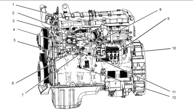
Sensor Locations for the Engine
The illustrations in this section show the typical
locations of the sensors for the industrial engine.
Specific engines may appear different from the
illustration due to differences in applications.
Illustration 7
g02974017
Typical example
(1) Exhaust Gas Recirculation (EGR) valve
(2) Inlet air temperature sensor
(3) Inlet manifold air pressure sensor
(4) Water in fuel sensor
(5) Engine oil temperaturesensor
(9) Control module
(10) Crankshaft position sensor
(11) Coolant jacket heater
(6) Injection pressure regulator
(7) Engine fuel pressure sensor
(8) Air inlet heater
(12) Engine oil pressure sensor
This document has been printed from SPI2. NOT FOR RESALE.
![]()
![]()
KENR8774
21
Electronic Troubleshooting
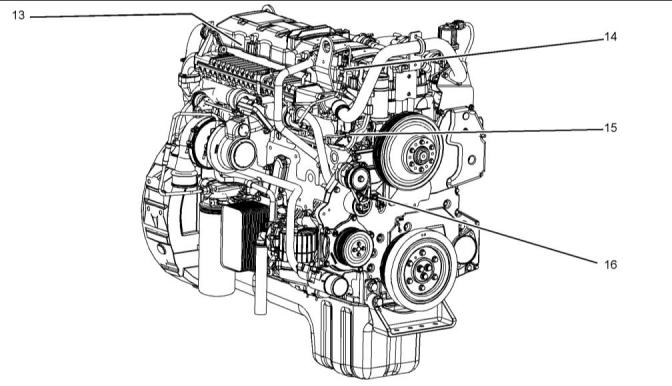
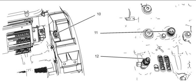
Illustration 8
g02976178
Typical example
(13) Injection control pressure sensor
(internal)
(14) Exhaust back pressure sensor
(15) Engine coolant temperature sensor
(16) Camshaft position sensor
This document has been printed from SPI2. NOT FOR RESALE.
![]()
![]()
22
KENR8774
Electronic Troubleshooting
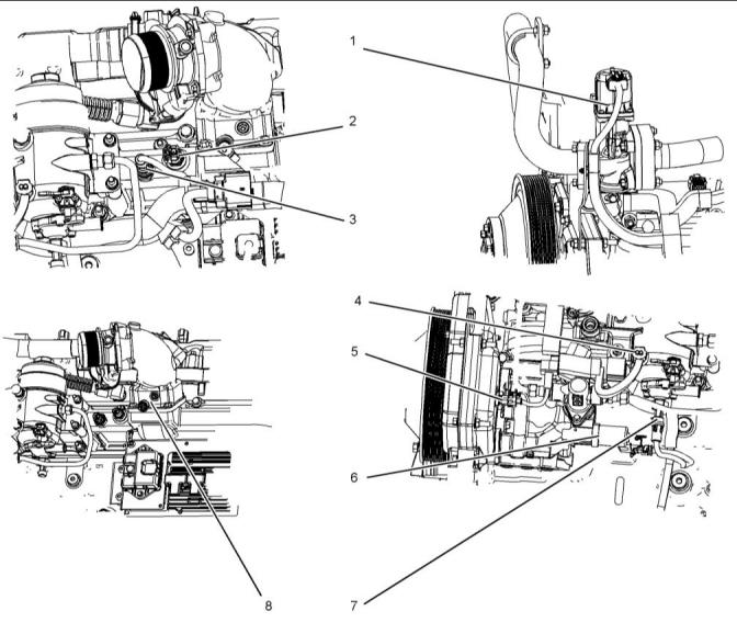
Illustration 9
g02732035
Typical example
(1) EGR valve
(2) Inlet air temperature sensor
(3) Inlet manifold air pressure sensor
(4) Water in fuel sensor
(5) Engine oil temperaturesensor
(6) Injection pressure regulator
(7) Engine fuel pressure sensor
(8) Inlet Air Heater (IAH)
This document has been printed from SPI2. NOT FOR RESALE.
![]()
![]()
KENR8774
23
Electronic Troubleshooting
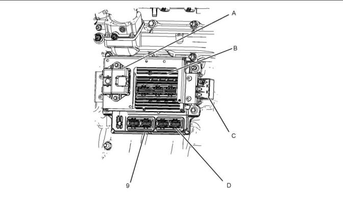
Illustration 10
g02732036
Typical example
(9) Control module
(A) EGR valve control module
(B) Injection Drive Module (IDM)
(C) IAH relay
(D) Electronic Control Module (ECM)
Illustration 11
g02976197
Typical example
(10) Crankshaft position sensor
(11) Coolant jacket heater
(12) Engine oil pressure sensor
This document has been printed from SPI2. NOT FOR RESALE.
![]()
![]()
![]()
24
KENR8774
Electronic Troubleshooting
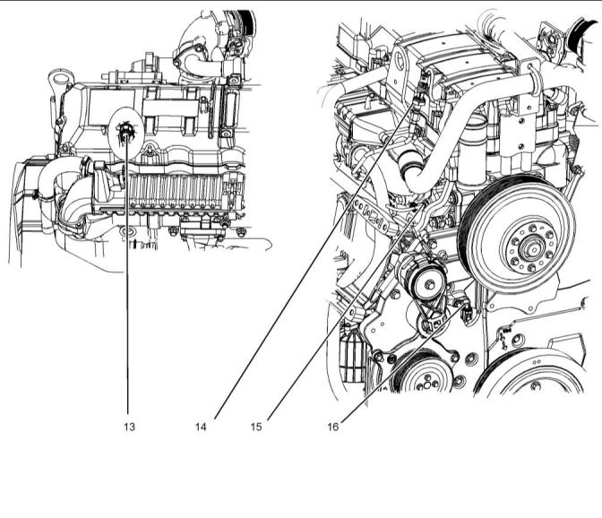
Illustration 12
g02976216
Typical example
(13) Injection control pressure sensor
(14) Exhaust back pressure sensor
(15) Coolant temperature sensor
(16) Camshaft position sensor
This document has been printed from SPI2. NOT FOR RESALE.
![]()
![]()
KENR8774
25
Electronic Troubleshooting
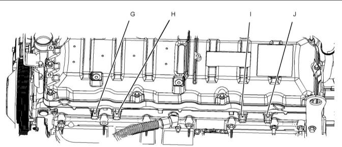
Illustration 13
g02976217
Typical example
(G) Injection control pressure connection
(H) Connector for injectors 1 and injector 2
(I) Connector for injectors 3 and injector 4
(J) Connector for injectors 5 and injector 6
This document has been printed from SPI2. NOT FOR RESALE.
![]()
![]()
26
KENR8774
Electronic Troubleshooting
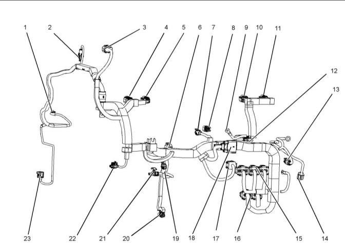
Wiring Harness
Illustration 14
g02740876
(1) Coolant temperature
(2) Exhaust back pressure
(3) EGR valve
(4) Injection control
(5) Injectors 1 and 2
(6) Water in fuel
(9) Inlet heater terminal
(10) Injectors 3 and 4
(11) Injectors 5 and 6
(12) Plug for inlet heater
(13) Relay
(14) Crankshaft position
(15) Injector drive connections
(16) ECM
(17) EGR control module
(18) Customer connection
(19) Low-pressure fuel
(20) Engine oil pressure
(21) Injection pressure regulator
(22) Oil temperature
(7) Inlet manifold air pressure
(8) Inlet air temperature
(23) Camshaft position connection
This document has been printed from SPI2. NOT FOR RESALE.
![]()
![]()
KENR8774
27
Electronic Troubleshooting
i05513190
Engine Wiring
Information
Schematic Diagrams
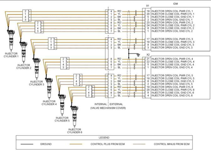
Illustration 15
g02212713
Schematic Diagram for the Injectors
This document has been printed from SPI2. NOT FOR RESALE.
![]()
![]()
28
KENR8774
Electronic Troubleshooting
Illustration 16
g02216053
Schematic Diagram for the Engine
This document has been printed from SPI2. NOT FOR RESALE.

![]()
![]()
KENR8774
29
Electronic Troubleshooting
Note: The EGR controller and EGR valve are
applicable to the 1600D engine only.
Illustration 17
g02223493
Schematic Diagram for a Typical Application
This document has been printed from SPI2. NOT FOR RESALE.

![]()
![]()
30
KENR8774
Electronic Troubleshooting
i05352877
ECM Harness Connector
Terminals
The Electronic Control Module (ECM) uses four
connectors that have 24 terminals to interface to the
wiring harness.
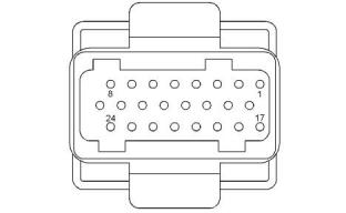
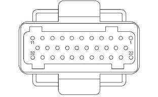
The Injector Driver Module (IDM) uses two
connectors that have 24 terminals and one connector
that has 32 terminals to interface to the wiring
harness.
Illustration 18
g03390396
Layout of the 24-pin connectors (view from the front)
Illustration 19
g03390435
Layout of the 32-pin IDM connector (view from the
front)
This document has been printed from SPI2. NOT FOR RESALE.
![]()
![]()
![]()
![]()
![]()
KENR8774
31
Programming Parameters
Programming Parameters
7. Turn the ignition keyswitch to the ON position and
the OFF position when instructed to ensure that
the flash file is saved.
8. Only disconnect the 27610401 CA3
Communication Adaptor Kit from the ECM when
the “Successfully Programmed” message
appears.
i05583509
Programming Parameters
The electronic service tool can be used to view
certain parameters that can affect the operation of the
engine. The electronic service tool can also be used
to change certain parameters. The parameters are
stored in the Electronic Control Module (ECM).
i05585209
Flash Programming
Flash Programming – A method of loading a flash
file into the Electronic Control Module (ECM) and the
Injector Driver Module (IDM)
Flash Programming a Flash File
1. Contact “PartsHelpdesk@Perkins.com ” in order to
obtain the correct flash file. The flash file will be
sent via e-mail.
2. Use a 27610404 Power-Up Harness to provide
power to the ECM during the flash programming
procedure.
Note: If the 27610404 Power-Up Harness is not
available, the ECM and IDM must be correctly
connected to the batteries. The ECM must be able to
control the main power relay and there must be a
switch on the supply to ECM pin X3:3 and IDM pin
X3:9. The main power to each module must be via
relays that are switched by the modules. Refer to
Troubleshooting, “Engine Wiring Information”.
3. Connect the ECM to the computer using the
27610401 CA3 Communication Adaptor Kit.
Refer to Troubleshooting, “Electronic Service
Tools” for more information.
4. Start the flash file program that was sent via e-mail.
Note: The flash file is a self-contained executable file.
No other software is required other than the CA3
Communication Adaptor drivers that are included with
the 27610401 CA3 Communication Adaptor Kit.
5. Select the “Perkins CA3” from the “Cables” drop-
down box.
6. Follow the on-screen instructions in order to install
the flash file.
This document has been printed from SPI2. NOT FOR RESALE.
![]()
32
KENR8774
Symptom Troubleshooting
Symptom Troubleshooting
i05352934
Alternator Is Noisy
Note: This symptom is not an electronic system fault.
Refer to Systems Operation, Testing and Adjusting
for information on possible electrical causes of this
condition.
Probable Causes
• Alternator drive belt and tensioner
• Alternator mounting bracket
• Alternator drive pulley
• Alternator bearings
Recommended Actions
Note: The procedures have been listed in order of
probability. Complete the procedures in order.
This document has been printed from SPI2. NOT FOR RESALE.
![]()
KENR8774
33
Symptom Troubleshooting
Table 3
TroubleshootingTest Steps
Values
Results
1. Alternator Drive Belt and Tensioner
Drive belt
Result: The alternator drive belt is in good condition and
the belt tension is correct.
A. Inspect the condition of the alternator drive belt.
Proceed to Test Step 2.
B. Check the belt tension. If necessary, check the automatic
belt tensioner.
Result: The alternator drive belts are not in good condition
or the belt tension is incorrect.
Note: Excessive belt tension can result in damage to the
alternator.
If the alternator drive belts are worn or damaged, replace
the belts. Refer to Disassembly and Assembly for the cor-
rect procedure.
If necessary, replace the automatic belt tensioner. Refer to
Disassembly and Assembly for the correct procedure.
Result: The alternator drive belts are in good condition and
the belt tension is correct.
Proceed to Test Step 2.
2. Alternator MountingBracket
AlternatorMounting Result: The alternator mounting bracket is cracked and
Bracket
distorted.
A. Inspect the alternator mounting bracket for cracks and
distortion.
Repair the mounting bracket or replace the mounting
bracket.
Note: The repair/replacement will ensure that the alternator
drive belt and the alternator drive pulley are in alignment.
Result: The alternator mounting bracket is OK.
Proceed to Test Step 3.
3. Alternator Drive Pulley
Alternator Drive
Pulley
Result: There is excessive wear on the alternator drive
pulley.
A. Check the condition of the alternator drive pulley. Look for
deep grooves that have been worn into the pulley by the belt.
Check that the nut for the pulley has not become loose.
Replace the pulley.
Result: The alternator drive pulley nut was loose.
Tighten the nut.
Result: There is not excessive wear on the alternator drive
pulley.
Proceed to Test Step 4.
4. Alternator Bearings
Alternator bearings Result: The alternator bearings are not OK.
A. Check the alternator bearings for signs of wear.
Repair the alternator or replace the alternator, as needed.
Refer to Disassembly and Assembly for the correct
procedure.
Result: The alternator bearings are OK.
Contact Perkins Global Technical Support.
This document has been printed from SPI2. NOT FOR RESALE.

![]()
34
KENR8774
Symptom Troubleshooting
i05354365
Alternator Problem
Note: This symptom is not an electronic system fault.
Probable Causes
• Alternator drive belt and tensioner
• Alternator
• Charging circuit
Recommended Actions
Note: The procedures have been listed in order of
probability. Complete the procedures in order.
Table 4
TroubleshootingTest Steps
Values
Results
Result: The alternator drive belts are not in good condition
1. Alternator Drive Belt and Tensioner
Drive belt
or the belt tension is incorrect.
A. Inspect the condition of the alternator drive belt.
B. Check the belt tension. Check the automatic belt tensioner.
If the alternator drive belts are worn or damaged, replace
the belts. Refer to Disassembly and Assembly for the cor-
rect procedure.
Note: Excessive belt tension can result in damage to the
alternator.
If necessary, replace the automatic belt tensioner. Refer to
Disassembly and Assembly for the correct procedure.
Result: The alternator drive belts are in good condition and
the belt tension is correct.
Proceed to Test Step 2.
2. Alternator
Alternator
Result: The alternator is not operating correctly.
A. Verify that the alternator is operating correctly.
Repair the alternatoror replace the alternator, as necessary.
Refer to Disassembly and Assembly, “Alternator- Remove”
and Disassembly and Assembly, “Alternator- Install” for the
correct procedure.
Result: The alternator is operating properly.
Proceed to Test Step 3.
3. Charging Circuit
Charging circuit
Result: The charging circuit is not operating correctly.
A. Inspect the battery cables, wiring, and connections in the
charging circuit.
Clean all connections and tighten all connections. Replace
any faulty parts.
Result: The charging circuit is operating correctly.
Contact Perkins Global Technical Support.
This document has been printed from SPI2. NOT FOR RESALE.

![]()
KENR8774
35
Symptom Troubleshooting
i05354382
Battery Problem
Probable Causes
• Charging circuit
• Battery
• Auxiliary device
Recommended Actions
Complete the procedure in the order in which the
steps are listed.
Table 5
TroubleshootingTest Steps
Values
Results
1. Charging Circuit
Charging
circuit
Result: The charging circuit is not OK.
Repair the charging circuit, as necessary.
Result: The charging circuit is OK.
Proceed to Test Step 2.
A. Check that the battery charging circuit is operating correctly. Re-
fer to Troubleshooting, “AlternatorProblem”.
2. Battery
Battery
Result: The battery is not OK.
A. Verify that the battery is no longer able to hold a charge. Refer
to Systems Operation/Testing and Adjusting, “Battery - Test”.
Replace the battery. Refer to the Operation and Maintenance
Manual, “Battery - Replace”.
Result: The battery is OK.
Proceed to Test Step 3.
3. Auxiliary Device
Auxiliary
Device
Result: The battery has been drained by an auxiliary device
being left in the ON position.
A. Check if an auxiliary device has drained the battery by being left
in the ON position.
Charge the battery. Verify that the battery is able to maintain a
charge. Refer to Systems Operation/Testing and Adjusting for
the correct procedure.
Result: The battery has not been drained by an auxiliary de-
vice being left in the ON position.
Contact Perkins Global Technical Support.
This document has been printed from SPI2. NOT FOR RESALE.

![]()
36
KENR8774
Symptom Troubleshooting
i05355795
Coolant Contains Oil
Recommended Actions
Table 6
TroubleshootingTest Steps
Values
Results
1. Engine Cooling System
Oil Cooler
Result: A leak is found in the engine cooling system.
A. Inspect and test the engine cooling system for leaks. Refer
to Systems Operation, Testing, and Adjusting, “Cooling Sys-
tem” for the proper procedure.
Repair any leaks.
Flush the cooling system. Refer to the Operation and Main-
tenance Manual for the correct procedure. Refill the cooling
system with the correct coolant. Refer to the Operation and
Maintenance Manual for the recommended coolant and
capacities.
Refill the engine with the proper oil after the leak has been
repaired. Refer to the Operation and Maintenance Manual
for the correct oil capacities and viscosity.
Result: A leak was not found in the engine cooling system.
Contact Perkins Global Technical Support.
i05363437
Coolant Level Is Low
Use this procedure when the engine coolant level is
repeatedly found to be low or if the following
diagnostic code is active:
Table 7
Diagnostic Trouble Codes for Low Coolant Level
Code Description
DTC
Comments
323
Engine Coolant Level below warning/critical level
The Electronic Control Module (ECM) detects that the engine coolant is
low. When the Engine Warning Protection System (EWPS) mode is 3-
way protection, the engine will shut down.
After the shutdown, the engine can be restarted for 30 seconds.
The ECM will log the engine hours at the time of the occurrence.
When the coolant has returned to the correct level, the code will be-
come inactive.
Inspect the cooling system. Refer to Systems
Operation, Testing, and Adjusting, “Cooling System -
Test” for the correct procedure.
This document has been printed from SPI2. NOT FOR RESALE.

![]()
KENR8774
37
Symptom Troubleshooting
i05355807
Coolant Temperature Is High
Table 8
Diagnostic Trouble Codes for High Coolant Temperature
DTC
DTC Description
Comments
The Electronic Control Module (ECM) detects that the engine cool-
ant temperatureis above 110° C (230° F).
321
Engine Coolant Temperatureabove warning level
The red engine lamp will come on.
The DTC will become inactive when the coolant temperature is less
than 110° C (230° F).
The Electronic Control Module (ECM) detects that the engine cool-
ant temperatureis above 112° C (234° F).
322
325
Engine Coolant Temperatureabove critical level
The red engine lamp will come on.
The DTC will become inactive when the coolant temperature is less
than 112° C (234° F).
The Electronic Control Module (ECM) detects that the engine cool-
ant temperatureis above 107° C (225° F).
Power reduced, matched to cooling system performance
The engine will be derated.
The DTC will become inactive when the coolant temperature is less
than 107° C (225° F).
Probable Causes
• Diagnostic codes
• Coolant level
• Coolant temperature sensor
• Radiator and hoses
• Radiator cap and pressure relief valve
• Water temperature regulator
• Engine cooling fan
• Injector sleeves
• Quality of coolant
• Coolant pump
• Cylinder head gasket
• Cylinder head
Recommended Actions
Note: The procedures have been listed in order of
probability. Complete the procedures in order.
This document has been printed from SPI2. NOT FOR RESALE.

![]()
38
KENR8774
Symptom Troubleshooting
Table 9
TroubleshootingTest Steps
Values
Results
1. DiagnosticCodes
Diagnostic
Codes
Result: Diagnostic codes are not present.
Return the unit to service.
A. Use the electronic service tool to check for diagnostic codes
that relate to the temperaturein the cooling system.
Result: Diagnostic codes are present.
Proceed to Test Step 2.
2. Coolant Level
Engine coolant
level
Result: The engine coolant level is low.
A. Check the coolant level.
Check the cooling system for leaks. Refer to Troubleshoot-
ing, “Coolant Level is Low” for additional information. Re-
pair any leaks immediately.
Result: The engine coolant level is OK.
Proceed to Test Step 3.
3. Coolant Temperature Sensor
Coolant tem-
Result: The temperaturesensor is not accurate.
perature sensor
A. Compare the reading for the coolant temperatureon the elec-
tronic service tool to the reading for the coolant temperature on a
calibrated test gauge.
Troubleshoot the circuit and the coolant temperature sen-
sor. Refer to Troubleshooting, “Sensor Signal (Analog, Pas-
sive) - Test”.
Result: The temperaturesensor is reading accurately.
Proceed to Test Step 4.
4. Radiator and Hoses
Radiator and
hoses
Result: The radiator fins are blocked or damaged.
Remove any dirt and/or debris and straighten any bent fins.
Result: The radiator has internal blockage.
Remove the blockage.
A. Check the radiator fins for dirt, debris, and/or damage.
B. Check for collapsed hoses and/or other restrictions.
C. Check the radiator for internal blockage.
Result: The radiator fins are not damaged and the radiator
does not have an internal blockage.
Proceed to Test Step 5.
5. Radiator Cap and Pressure Relief Valve
Radiator cap
Result: The pressure relief valve and/or the water tempera-
ture regulator are not operating properly.
A. Pressure-test the cooling system. Refer to Systems Operation,
Testing, and Adjusting, “Cooling System” for the correct
procedure.
Clean the components or replace the components.
Result: The pressure relief valve and/or the water tempera-
B. Check that the seating surfaces of the pressure relief valve , and
the radiator cap are clean and undamaged.
ture regulator are operating properly.
Proceed to Test Step 6.
C. Check operation of the pressure relief valve and/or the water
temperature regulator.
6. Water Temperature Regulator
Water Temper-
ature Regulator
(continued)
This document has been printed from SPI2. NOT FOR RESALE.

![]()
KENR8774
39
Symptom Troubleshooting
(Table 9, contd)
TroubleshootingTest Steps
Values
Results
Check the water temperatureregulator for correct operation. Refer
to Systems Operation, Testing, and Adjusting, “Cooling System”
for the proper procedure.
Result: The water temperatureregulator is not operating
correctly.
Replace the water temperature regulator. Refer to Disas-
sembly and Assembly, “Water TemperatureRegulator - Re-
move and Install”.
Result: The water temperatureregulator is operating
correctly.
Proceed to Test Step 7.
7. Engine Cooling Fan
Fan and drive Result: The drive belt is not tensioned correctly.
belt
A. Check for a loose drive belt.
Check the automatic tensioner and replace the tensioner, if
necessary.
Note: A loose fan drive belt will cause a reduction in the air flow
across the radiator.
Result: The fan is damaged.
B. Check the engine cooling fan for damage.
Repair the fan or replace the fan, as necessary. Refer to
Disassembly and Assembly, “Fan - Remove and Install”.
Result: The fan is OK and the fan belt is tensioned
correctly.
Proceed to Test Step 8.
8. Injector Sleeves
Result: There were no bubbles present in the coolant. The
coolant is not discolored.
A. Switch off the engine and allow the engine to cool to below nor-
mal working temperature. Remove the pressure cap for the cool-
ant system. Start the engine and inspect the coolant for the
presence of bubbles or discoloration of the coolant.
Combustion gases are not leaking into the coolant.
Contact Perkins Global Technical Support.
Note: If bubbles are present in the coolant or the coolant is discol-
ored, combustion gases may be entering the cooling system.
Result: Coolant is leaking around the injector sleeves.
Replace any leaking injector sleeves. Refer to Disassembly
and Assembly, “Electronic Unit Injector Sleeve - Remove”
and Disassembly and Assembly, “Electronic Unit Injector
Sleeve - Install”.
B. Remove the fuel injectors. Refer to Disassembly and Assembly,
“Electronic Unit Injector - Remove”.
C. Install a radiator pressure tester with the appropriate adaptor.
D. Pressurize the cooling system to 96 kPa (14 psi).
E. Look for coolant leaking around the injector sleeves.
Result: There is no coolant leaking around the injector
sleeves.
Proceed to Test Step 9.
9. Quality of Coolant
Coolant
Result: The coolant is not of an acceptable quality.
A. Check the quality of the coolant. Refer to the Operation and
Maintenance Manual, “Refill Capacities and Recommendations -
Coolant”.
Drain and refill the coolant system with coolant of the cor-
rect quality. Refer to the Operation and Maintenance Man-
ual, “Refill Capacities and Recommendations - Coolant”.
Result: The coolant is of an acceptable quality.
Proceed to Test Step 10.
10. Inspection of the Coolant Pump
Coolant pump
(continued)
This document has been printed from SPI2. NOT FOR RESALE.
免費熱線
400-100-8969???15088860848
400-100-8969???15088860848
機組銷售
0574-26871589? 15267810868
0574-26871589? 15267810868
配件銷售
0574-26886646? 15706865167
0574-26886646? 15706865167
維修熱線
0574-26871569 18658287286
0574-26871569 18658287286
手機端

微信公眾號