 English
 Espaol
 Franais
 阿拉伯
阿拉伯 中文(簡(jiǎn))
 Deutsch
 Italiano
 Português
 日本
日本 韓國
韓國 български
 hrvatski
 esky
esky Dansk
Dansk Nederlands
 suomi
suomi Ελληνικ
 印度
印度 norsk
norsk Polski
 Roman
Roman русский
 Svenska
 珀金斯Perkins2506-15發(fā)動(dòng)機(jī)測(cè)試調(diào)整手冊(cè),珀金斯Perkins2506-15發(fā)動(dòng)機(jī)測(cè)試調(diào)整手冊(cè)技術(shù)支持中心,珀金斯Perkins2506-15發(fā)動(dòng)機(jī)測(cè)試調(diào)整手冊(cè)代理商,珀金斯Perkins2506-15發(fā)動(dòng)機(jī)測(cè)試調(diào)整手冊(cè)銷售服務(wù)中心,珀金斯Perkins2506-15發(fā)動(dòng)機(jī)測(cè)試調(diào)整手冊(cè)價(jià)格規(guī)格資料查詢,寧波日昕動(dòng)力科技有限公司

首頁
產(chǎn)品展示>珀金斯Perkins2506-15發(fā)動(dòng)機(jī)測(cè)試調(diào)整手冊(cè)
珀金斯Perkins2506-15發(fā)動(dòng)機(jī)測(cè)試調(diào)整手冊(cè)
詳細(xì)描述
Systems Operation
Testing and Adjusting
2506-15 Industrial Engine
M G A (Engine)
MGB (Engine)
M G D (Engine)
Table of Contents
Charging System - Test ........................................ 54
Electric Starting System - Test .............................. 55
Index Section
Systems Operation Section
Index ..................................................................... 56
General Information ................................................ 4
Electronic Control System Components ................. 6
Fuel System ........................................................... 8
Air Inlet and Exhaust System ............................... 12
Lubrication System .............................................. 14
Cooling System .................................................... 16
Basic Engine ......................................................... 17
Electrical System ................................................. 18
Testing and Adjusting Section
Testing and Adjusting
Belt Tension Chart ................................................ 22
Fuel System
Fuel System - Inspect ........................................... 23
Air in Fuel - Test .................................................... 23
Electronic Unit Injector - Adjust ............................. 24
Electronic Unit Injector - Test ................................ 24
Finding Top Center Position for No. 1 Piston ........ 25
Fuel Quality - Test ................................................. 26
Fuel System - Prime ............................................. 26
Fuel System Pressure - Test ................................. 27
Gear Group (Front) - Time .................................... 28
Air Inlet and Exhaust System
Air Inlet and Exhaust System - Inspect ................. 31
Turbocharger - Inspect .......................................... 32
Exhaust Temperature - Test .................................. 34
Engine Crankcase Pressure (Blowby) - Test ........ 35
Engine Valve Lash - Inspect/Adjust ...................... 35
Lubrication System
Engine Oil Pressure - Test .................................... 37
Excessive Bearing Wear - Inspect ........................ 39
Excessive Engine Oil Consumption - Inspect ....... 39
Increased Engine Oil Temperature - Inspect ........ 40
Cooling System
Cooling System - Check (Overheating) ................ 41
Cooling System - Inspect ...................................... 42
Cooling System - Test ........................................... 43
Water Temperature Regulator - Test ..................... 45
Water Pump - Test ................................................ 46
Basic Engine
Piston Ring Groove - Inspect ................................ 47
Connecting Rod Bearings - Inspect ...................... 47
Main Bearings - Inspect ........................................ 47
Cylinder Block - Inspect ........................................ 47
Cylinder Liner Projection - Inspect ........................ 48
Flywheel - Inspect ................................................. 50
Flywheel Housing - Inspect ................................... 51
Vibration Damper - Check .................................... 53
Electrical System
Battery - Test ......................................................... 54
This document has been printed from SPI². Not for Resale
![]()
4
KENR6231
Systems Operation Section
Systems Operation Section
i02550114
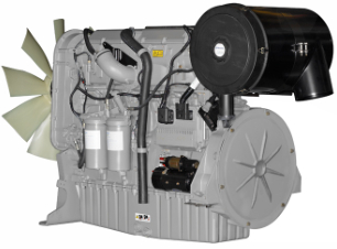
General Information
The following model views show the 2506 Engine
features. Due to individual applications, your engine
may appear different from the illustrations.
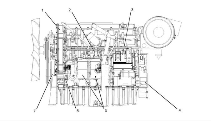
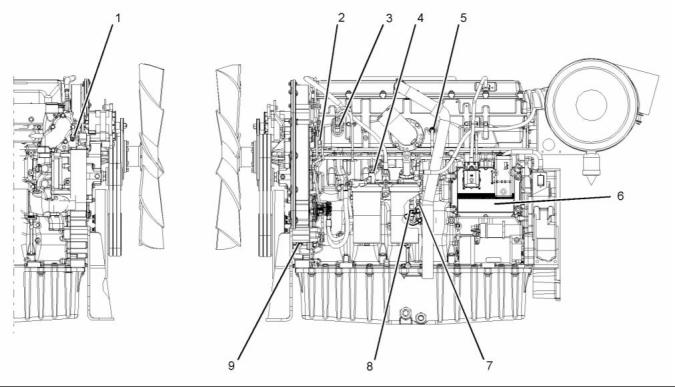
g01288248
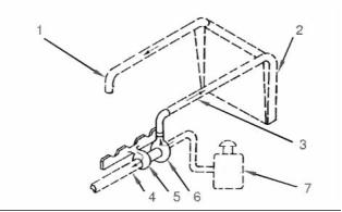
Illustration 1
Typical example
Left side view
(1) Front timing gear housing
(2) Fuel priming pump
(4) Flywheel housing
(5) Fuel filters
(7) Vibration Damper
(3) Electronic Control Module (ECM)
(6) Fuel transfer pump
This document has been printed from SPI². Not for Resale
![]()
![]()
KENR6231
5
Systems Operation Section
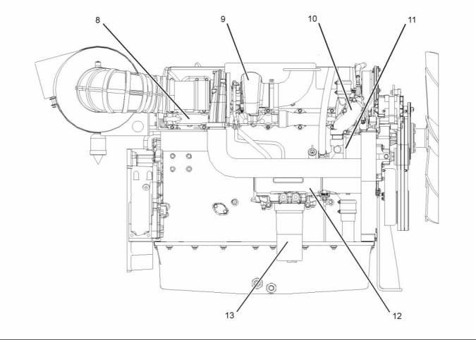
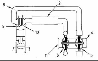
g01288247
Illustration 2
Typical example
Right side view
(8) Exhaust manifold
(9) Turbocharger
(10) Temperature regulator housing
(11) Water pump
(12) Oil cooler
(13) Oil filter
Starting the Engine
Cold mode operation varies the fuel injection amount
for white smoke cleanup. Cold mode operation also
varies the timing for white smoke cleanup. The
engine operating temperature is usually reached
before the walk-around inspection is completed.
The Electronic Control Module (ECM) will
automatically provide the correct amount of fuel that
is necessary to start the engine. If the engine fails
to start in 30 seconds, the starter switch should be
released. The starting motor should be allowed to
cool for 30 seconds before being used again.
Cold Mode Operation
The ECM will set the cold start strategy when the
coolant temperature is below 18 °C (64 °F).
Cold mode operation will be deactivated when any of
the following conditions have been met:
• Coolant temperature reaches 18 °C (64 °F).
• The engine has been running for fourteen minutes.
This document has been printed from SPI². Not for Resale
![]()
![]()
6
KENR6231
Systems Operation Section
i02589727
Electronic Control System
Components
g01279775
Illustration 3
(1) Coolant temperature sensor
(2) Camshaft position sensor
(3) Inlet manifold pressure sensor
(4) Fuel temperature sensor
(7) Engine oil pressure sensor
(8) Atmospheric pressure sensor
(9) Crankshaft position sensor
(5) Inlet manifold temperature sensor
(6) Electronic control module (ECM)
The electronic control system is integrally designed
into the engine’s fuel system and the engine’s air
inlet and exhaust system in order to electronically
control the fuel delivery and the injection timing. The
electronic control system provides increased timing
control and fuel air ratio control in comparison to
conventional mechanical engines. Injection timing
is achieved by precise control of injector firing time,
and engine rpm is controlled by adjusting the firing
duration. The Electronic Control Module (ECM)
energizes the solenoid in the unit injector in order to
start the injection of fuel. Also, the ECM de-energizes
the unit injector solenoids in order to stop injection
of fuel. Refer to Systems Operation, Testing and
Adjusting, “Fuel System” for a complete explanation
of the fuel injection process.
• Controls
• Outputs
An input component is one that sends an electrical
signal to the ECM. The signal that is sent varies in
one of the following ways:
• Voltage
• Frequency
• Pulse width
The variation of the signal is in response to a change
in some specific system of the vehicle. The ECM
sees the input sensor signal as information about the
condition, environment, or operation of the vehicle.
The engine uses the following types of electronic
components:
• Inputs
This document has been printed from SPI². Not for Resale
![]()
![]()
KENR6231
7
Systems Operation Section
A control component (ECM) receives the input
signals. Electronic circuits inside the control
component evaluate the signals from the input
components. These electronic circuits also supply
electrical energy to the output components of the
system. The electrical energy that is supplied to
the output components is based on predetermined
combinations of input signal values.
An output component is one that is operated by a
control module. The output component receives
electrical energy from the control component. The
output component uses that electrical energy in one
of two ways. The output component can use that
electrical energy in order to perform work. The output
component can use that electrical energy in order to
provide information.
This document has been printed from SPI². Not for Resale
![]()
8
KENR6231
Systems Operation Section
i02550058
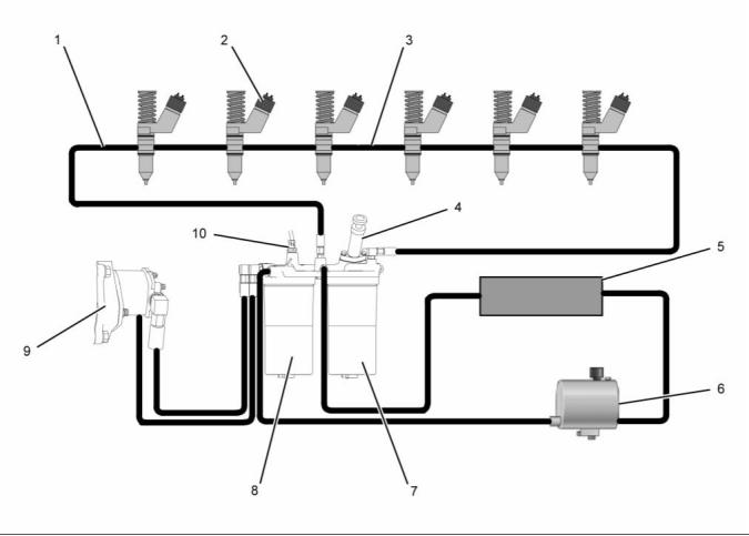
Fuel System
g01282152
Illustration 4
Fuel system schematic
(1) Fuel return line
(2) Electronic unit injectors
(3) Fuel gallery
(6) Fuel tank
(7) Secondary fuel filter
(8) Primary fuel filter
(4) Fuel priming pump
(5) Fuel cooler
(9) Fuel transfer pump
(10) Fuel temperature sensor
The fuel supply circuit is a conventional design for
engines with electronic unit injection. A fuel tank (6)
is used to store the fuel prior to use by the engine. A
primary fuel filter/water separator (8) is placed into
the fuel supply circuit in order to remove large debris
from the fuel. This debris may have entered the
fuel tank during fueling. The debris may have also
entered the fuel tank through the vent for the fuel
tank. The primary filter element also separates water
from the fuel. The water is collected in the bowl at the
bottom of the primary fuel filter/water separator.
Note: The inlet fuel temperature to the fuel transfer
pump must not exceed 79 °C (175 °F) when the
engine has reached normal operating temperature.
Fuel temperatures above 79 °C (175 °F) will reduce
the life of the fuel transfer pump check valves. The
fuel efficiency and the engine power output are
reduced when the fuel temperature increases from
30 °C (86 °F) to 70 °C (158 °F).
This document has been printed from SPI². Not for Resale
![]()
![]()
KENR6231
9
Systems Operation Section
Fuel from the tank (6) flows to the fuel filter base.
The fuel filter base contains the primary fuel filter
and the secondary fuel filter. The fuel flows through
cored passages in the fuel filter base. The fuel
priming pump (4) is mounted on the fuel filter base.
The fuel priming pump is used in order to manually
pump the fuel into the fuel system after the system,
or parts of the system have been drained. The fuel
priming pump is used in order to refill the fuel system
after air has been introduced into the system. For
more information on priming the fuel system, refer
to Systems Operation, Testing and Adjusting, “Fuel
System - Prime”.
The fuel exits the fuel gallery and returns to the fuel
filter base. A pressure regulating valve is located in
the fuel filter base. The pressure regulating valve
regulates the pressure for the fuel system. A sufficient
amount of back pressure is maintained in the system
in order to ensure a continuous availability of fuel to
the electronic unit injectors. The fuel flows from the
fuel filter base to the fuel cooler (5). The fuel flows
from the fuel cooler (5) back to the tank (6).
Fuel System Electronic Control
Circuit
As the fuel flows through cored passages in the fuel
filter base, the fuel is directed into the primary fuel
filter (8). Fuel flows out of the fuel filter and returns
to the passages in the fuel filter base. Prior to exiting
the fuel filter base, the fuel temperature is sampled
by the fuel temperature sensor (10). The signals
that are generated by the sensors are used by the
engine control in order to monitor the condition of the
engine’s components.
The fuel flows from the fuel filter base to the fuel
transfer pump (9). The fuel transfer pump (9) is a gear
type pump with fixed clearances. The fuel transfer
pump (9) incorporates an internal relief valve that
protects the fuel system from extreme pressure. In
the case of extreme pressure, fuel is redirected back
to the inlet of the fuel transfer pump (9). An outlet
check valve is used in order to prevent pressurized
fuel leakage back through the pump. The fuel transfer
pump (9) is located in the front of the engine. The fuel
transfer pump (9) is driven by the front gear train.
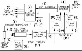
g00451841
Illustration 5
Electronic governor
(1) Signals to the electronic unit injectors
(2) Fuel injection control
(3) Fuel position
(4) Electronic governor
(5) Desired rpm
(6) Coolant temperature
(7) TC for No. 1 cylinder
(8) FRC fuel position
The fuel flows from the fuel transfer pump (9) to the
secondary fuel filter (7). The fuel is filtered in order
to remove small abrasive particles that will cause
premature wear to fuel system components. The fuel
flows from the secondary fuel filter (7) to the fuel filter
base.
(9) Rated fuel position
(10) FCR maps
(11) Torque maps
(12) Engine speed/timing sensor
(13) Engine speed/timing signals’ interpreter
(14) Engine rpm
(15) Coolant temperature sensor
(16) Boost pressure sensor
(17) Boost pressure
The fuel is then directed from the fuel filter base
through the fuel return line (1) to fuel manifold (3) that
runs the length of the cylinder head. A continuous
flow of fuel is supplied to the electronic unit injectors
(2) in order to perform the following tasks:
The injection pump, the fuel lines, and the nozzles
that are used in the traditional Perkins diesel engines
have been replaced with an electronically controlled,
mechanically actuated electronic unit injector in each
cylinder. A solenoid on each injector controls the
amount of fuel that is delivered by the injector. An
Electronic Control Module (ECM) sends a signal to
each injector solenoid in order to provide complete
control of the engine.
• Supply fuel for injection
• Remove excessive heat from the injectors.
• Remove air that may accumulate in the fuel
system.
This document has been printed from SPI². Not for Resale
![]()
![]()
10
KENR6231
Systems Operation Section
Fuel Injection
Electronic Unit Injector Mechanism
The ECM controls the amount of fuel that is injected
by varying the signals that are sent to the injectors.
The ECM sends a high voltage signal to the solenoid
in order to energize the solenoid. The injectors
will inject fuel only while the injector solenoid is
energized. By controlling the timing and the duration
of the voltage signal, the ECM can control injection
timing and the amount of fuel that is injected.
The ECM sets certain limits on the amount of fuel that
can be injected. “FRC” is a limit which controls the
amount of air and of fuel for the purpose of emission
control. This limit is based on the boost pressure.
When the ECM senses a higher boost pressure, the
ECM increases the “FRC” limit. “Rated Fuel Pos” is
a limit that is based on the horsepower rating of the
engine. This is similar to the rack stops and to the
torque spring on a mechanically governed engine.
“Rated Fuel Pos” provides horsepower and torque
curves for a specific engine family and for a specific
engine rating. All of these limits are programmed into
the personality module by the factory. These limits
are not programmable by the service technician.
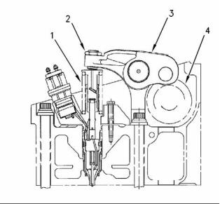
g00291269
Illustration 6
Electronic unit injector mechanism
(1) Electronic unit injector
(2) Adjusting nut
Injection timing depends on three factors: the engine
speed (rpm), the engine load, and the operational
conditions of the engine. The ECM determines the
top center position of No. 1 cylinder from the signal
that is provided by the engine speed/timing sensor.
The ECM decides when the injection should occur
relative to the top center position. The ECM then
provides the signal to the electronic unit injector at
the desired time.
(3) Rocker arm assembly
(4) Camshaft lobe
The electronic unit injector mechanism provides
the downward force that is required to pressurize
the fuel in the electronic unit injector pump. The
electronic unit injector (1) allows fuel to be injected
into the combustion chamber with precise timing.
Movement is transmitted from the camshaft lobe (4)
for the electronic unit injector through the rocker arm
assembly (3) to the top of the electronic unit injector.
The adjusting nut (2) allows the injector lash to be
adjusted. For the proper setting of the injector lash,
refer to the topic on adjustment of the electronic unit
injector in Systems Operation, Testing and Adjusting,
“Electronic Unit Injector - Adjust”.
This document has been printed from SPI². Not for Resale
![]()
![]()
KENR6231
11
Systems Operation Section
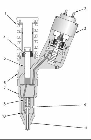
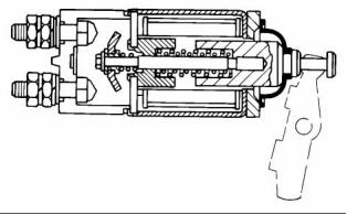
Electronic Unit Injector
As the electronic unit injector mechanism transfers
the force to the top of the electronic unit injector,
spring (1) is compressed and plunger (4) is driven
downward. This action displaces fuel through the
valve in solenoid valve assembly (3), and into the
return manifold to the fuel tank. As the plunger travels
downward, the passage in barrel (5) is closed by the
outside diameter of the plunger. The passages within
body (10) and along check valve (11) to the injector
tip already contain fuel for injection. After the passage
in the plunger barrel is closed, the injector is ready for
injection at any time. The start of injection relies on
the software in the Electronic Control Module (ECM).
When the solenoid valve assembly is energized
from a signal across solenoid connection (2), the
valve closes and fuel pressure is elevated in the
injector tip. Injection begins at 34500 ± 1900 kPa
(5000 ± 275 psi) as the force of spring (8) above
spacer (9) is overcome. The check valve begins
to lift from the valve seat. The pressure continues
to rise as the plunger cycles through a full stroke.
After the correct amount of fuel has been discharged
into the cylinder, the ECM removes the signal to the
solenoid connection. The solenoid valve assembly
is de-energized and the valve in the solenoid valve
assembly is opened. The high pressure fuel is then
dumped through the spill port and into the fuel return
manifold. The fuel is then returned to the fuel tank.
The check valve in the injector tip seats as the
pressure in the tip decreases.
The duration of injection meters the fuel that is
consumed during the fuel injection process. Injection
duration is controlled by the governor logic that is
programmed into the ECM.
g00984466
Illustration 7
Electronic unit injector
(1) Spring
As the camshaft lobe rotates past the point of
maximum lobe lift, the force on top of the electronic
unit injector is removed and the spring for the injector
mechanism is allowed to expand. The plunger returns
to the original position. This uncovers the fuel supply
passage into the plunger barrel in order to refill the
injector pump body. The fuel at low pressure is again
allowed to circulate through the fuel injector body.
After circulating through the fuel injector body, the
fuel flows out of the spill port. This continues until the
solenoid valve assembly is re-energized for another
injection cycle.
(2) Solenoid connection to the Electronic Control Module (ECM)
(3) Solenoid valve assembly
(4) Plunger assembly
(5) Barrel
(6) Seal
(7) Seal
(8) Spring
(9) Spacer
(10) Body
(11) Check valve
Fuel at low pressure from the fuel supply manifold
enters the electronic unit injector at the fill port
through drilled passages in the cylinder head.
This document has been printed from SPI². Not for Resale
![]()
![]()
12
KENR6231
Systems Operation Section
i02550062
Air Inlet and Exhaust System
Air is forced from the aftercooler into inlet manifold
(1). The air flow from the inlet port into the cylinders
is controlled by inlet valves.
g00615497
Illustration 9
g01046036
Air inlet and exhaust system
Illustration 8
Air inlet and exhaust system schematic
(2) Aftercooler core
(4) Exhaust outlet
(1) Inlet to the engine
(5) Turbine side of turbocharger
(6) Compressor side of turbocharger
(8) Exhaust manifold
(9) Exhaust valve
(2) Aftercooler core
(3) Inlet air line
(4) Exhaust outlet from turbocharger
(5) Turbine side of turbocharger
(6) Compressor side of turbocharger
(7) Air cleaner
(10) Inlet valve
(11) Air inlet
Each cylinder has two inlet valves (10) and two
exhaust valves (9) in the cylinder head. The inlet
valves open on the inlet stroke. When the inlet valves
open, compressed air from the inlet port within the
inlet manifold is pushed into the cylinder. The inlet
valves close when the piston begins the compression
stroke. The air in the cylinder is compressed and the
fuel is injected into the cylinder when the piston is
near the top of the compression stroke. Combustion
begins when the fuel mixes with the air. The force of
combustion pushes the piston on the power stroke.
The exhaust valves open and the exhaust gases
are pushed through the exhaust port into exhaust
manifold (8). After the piston finishes the exhaust
stroke, the exhaust valves close and the cycle begins
again.
The engine components of the air inlet and exhaust
system control the quality of air and the amount of
air that is available for combustion. The components
of the air inlet and exhaust system are the following
components:
• Air cleaner
• Turbocharger
• Aftercooler
• Cylinder head
• Valves and valve system components
• Piston and cylinder
• Exhaust manifold
Exhaust gases from the exhaust manifold flow
into the turbine side of turbocharger (5). The high
temperature exhaust gases cause the turbocharger
turbine wheel to turn. The turbine wheel is connected
to the shaft that drives the compressor wheel.
Exhaust gases from the turbocharger pass through
exhaust outlet (4), through a muffler, and through an
exhaust stack.
The turbocharger compressor wheel pulls inlet air
through the air cleaner and into the air inlet. The air
is compressed and this causes the air to become hot.
The air flows through aftercooler core (2) and the
temperature of the compressed air lowers. This helps
to provide increased horsepower output. Aftercooler
core (2) is a separate cooler core that is mounted in
front of the engine radiator. The engine fan causes
ambient air to move across both cores. This cools the
turbocharged inlet air and the engine coolant.
This document has been printed from SPI². Not for Resale
![]()
![]()
![]()
KENR6231
13
Systems Operation Section
Turbocharger
Valves And Valve Mechanism
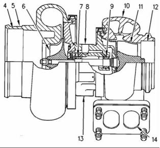
g01046041
g00291085
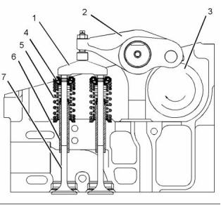
Illustration 11
Valve system components
Illustration 10
Turbocharger
(1) Valve bridge
(2) Rocker arm
(3) Camshaft
(4) Rotocoil
(4) Air inlet
(5) Compressor housing
(6) Compressor wheel
(7) Bearing
(5) Valve spring
(6) Valve guide
(7) Valve
(8) Oil inlet port
(9) Bearing
(10) Turbine housing
(11) Turbine wheel
(12) Exhaust outlet
(13) Oil outlet port
(14) Exhaust inlet
The valves and the valve mechanism control the flow
of inlet air into the cylinders during engine operation.
The valves and the valve mechanism control the flow
of exhaust gases out of the cylinders during engine
operation.
Turbocharger (3) is mounted to exhaust manifold (2)
of the engine. All of the exhaust gases go from the
exhaust manifold through the turbocharger.
The exhaust gases enter the turbocharger and the
turbine wheel is turned. Because the turbocharger
turbine wheel is connected by a shaft to the
turbocharger compressor wheel, the turbine wheel
and the compressor wheel turn at very high speeds.
The rotation of the compressor wheel pulls clean
air through the compressor housing air inlet. The
action of the compressor wheel blades causes a
compression of the inlet air. This compression allows
a larger amount of air to enter the engine. With more
air in the engine, the engine is able to burn more fuel.
The overall effect is an increase in power.
Bearing (7) and bearing (9) in the turbocharger use
engine oil that is under pressure for lubrication. The
lubrication for the bearings flows through oil inlet port
(8) and into the inlet port in the center section of the
turbocharger cartridge. The oil exits the turbocharger
through oil outlet port (13). The oil then returns to
the engine oil pan through the oil drain line for the
turbocharger.
This document has been printed from SPI². Not for Resale
![]()
![]()
![]()
14
KENR6231
Systems Operation Section
Rotocoils (4) cause the valves to rotate while the
engine is running. Valve rotation provides a longer
service life. Valve rotation also minimizes carbon
deposits on the valves.
Adjustable idler gear (10) is designed to provide the
required gear backlash between nonadjustable idler
gear (11) and camshaft gear (9). If the cylinder head is
removed, tolerances of the components will change.
The components that change are the cylinder head
and the head gasket. The adjustable idler gear must
be relocated. For information on setting the correct
backlash, refer to Systems Operation, Testing and
Adjusting, “Gear Group (Front) - Time”.
The camshaft drive gear has integral pendulums
which act as a vibration damper for the front gear
group. These pendulums are designed to counteract
the torsional forces from the injector pulses. This
eliminates vibration and noise. The engine also runs
smoother at all operating speeds.
i02550074
Lubrication System
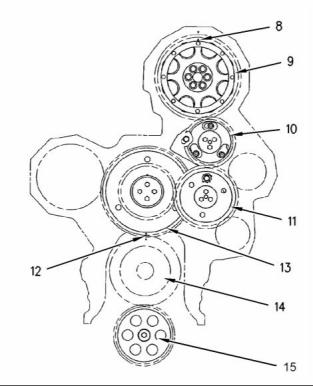
g01033757
Illustration 12
Components of the gear train
Lubrication System Components
(8) Timing mark
The lubrication system has the following components:
(9) Camshaft gear
(10) Adjustable idler gear
(11) Idler gear
• Oil pan
(12) Timing mark
(13) Cluster gear
(14) Crankshaft gear
(15) Oil pump gear
• Oil pump
• Oil cooler
The inlet valves and the exhaust valves are opened
by the valve mechanism. The inlet valves and
the exhaust valves are also closed by the valve
mechanism. This occurs as the rotation of the
crankshaft causes camshaft (3) to rotate. Camshaft
gear (9) is driven by a series of two idler gears (10)
and (11). Idler gear (11) is driven by cluster gear (13).
Cluster gear (13) is driven by crankshaft gear (14).
Timing mark (12) and timing mark (8) are aligned in
order to provide the correct relationship between the
piston and the valve movement.
• Oil filter
• Turbocharger oil lines
• Oil passages for the cylinder block
The camshaft has three lobes for each cylinder.
One lobe operates the inlet valves. A second lobe
operates the exhaust valves. The third lobe operates
the unit injector mechanism. The camshaft lobes turn
and the rocker arms move. Movement of the rocker
arms will make the inlet and exhaust valve bridges
move. These bridges allow one rocker arm to actuate
two valves at the same time. Each cylinder has two
inlet valves and two exhaust valves. Each valve has
one valve spring (5). The spring closes the valve.
This document has been printed from SPI². Not for Resale
![]()
![]()
KENR6231
15
Systems Operation Section
Oil Flow Through The Oil Filter And Oil
Cooler
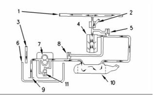
g00562383
Illustration 14
Oil flow when the engine Is cold.
g00562123
Illustration 13
Oil flow when the engine is warm.
(1) Oil manifold
(2) Oil supply line
(3) Oil return line
(4) Oil filter
(1) Oil manifold
(2) Oil supply line
(5) Bypass valve for the oil filter
(6) Oil pan
(3) Oil return line
(4) Oil filter
(7) Oil pump
(5) Bypass valve for the oil filter
(6) Oil pan
(8) Bypass valve for the oil cooler
(9) Suction lines
(7) Oil pump
(10) Oil cooler
(8) Bypass valve for the oil cooler
(9) Suction lines
(11) Bypass valve for the oil pump
(10) Oil cooler
When the engine is cold, oil is drawn from the oil
pan (6) through the suction lines (9) to the oil pump
(7). When the oil is cold, an oil pressure differential
in the bypass valves causes the bypass valves to
open. These bypass valves then provide immediate
lubrication to all of the engine components when cold
oil with high viscosity causes a restriction to oil flow
through the oil cooler (10) and the oil filter (4). The oil
pump then pushes the cold oil through the bypass
valve (8) for the oil cooler and through the bypass
valve (5) for the oil filter. The oil then goes to the oil
manifold (1) in the cylinder block and to the supply
line (2) for the turbocharger. Oil from the turbocharger
goes back through the oil return line (3) to the oil pan.
(11) Bypass valve for the oil pump
When the engine is warm, oil is drawn from the oil
pan (6) through the suction lines (9) to the oil pump
(7). The oil pump pushes the hot oil through the oil
cooler (10). The oil is then sent to the oil filter (4).
Oil from the oil filter is sent to the oil manifold (1) in
the cylinder block and to the oil supply line (2) for the
turbocharger. Oil from the turbocharger goes back
through the oil return line (3) to the oil pan.
When the oil is warm, an oil pressure differential in
the bypass valves also causes the bypass valves to
close. There is normal oil flow through the oil cooler
and the oil filter.
The bypass valves will also open when there is
a restriction in the oil cooler or the oil filter. This
prevents a restricted oil filter or a restricted oil cooler
from stopping the lubrication of the engine. The
system pressure is limited by the oil pump bypass
valve (11).
This document has been printed from SPI². Not for Resale
![]()
![]()
![]()
16
KENR6231
Systems Operation Section
Oil Flow In The Engine
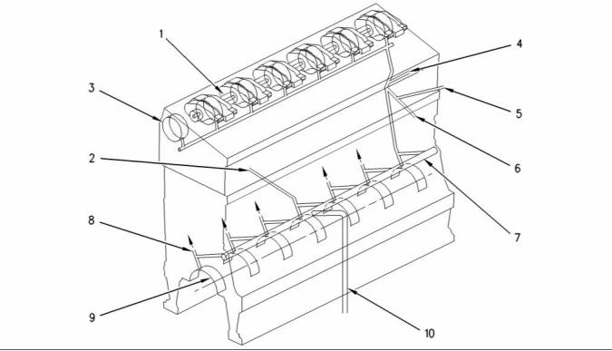
g00431790
Illustration 15
Engine oil flow schematic
(1) Rocker arm shaft
(5) Oil passage to the fixed idler stub shaft
(6) Oil passage to cluster idler gear
(7) Oil manifold
(9) Crankshaft main bearings
(10) Oil passage from filter
(2) Oil passage to air compressor
(3) Camshaft bearing journals
(4) Oil passage to adjustable idler gear
(8) Piston cooling jet
The oil from the oil manifold (7) is sent under
pressure through drilled passages to the crankshaft
main bearings (9). The oil flows through drilled holes
in the crankshaft. This oil lubricates the connecting
rod bearings. A small amount of oil is sent to the
piston cooling jets (8). The piston cooling jets spray
oil on the underside of the pistons.
Oil flows into the cylinder head via a hollow locating
dowel in the top deck of the cylinder block. Oil travels
to the camshaft bearing journals (3) and the three
center rocker arm shaft supports through drilled
passages in the cylinder head. The supports supply
oil to each rocker shaft. Oil flows to the bushings of
the fuel injector rocker arm through holes in the rocker
arm shaft (1). This same oil lubricates the valve and
the rollers. Oil flows through drilled passages in the
rocker arms. This oil lubricates the roller, the valve
bridge and the contact surfaces of the actuator of the
unit injector. Splash oil lubrication is used to lubricate
other components of the valve system.
Oil flows through passages in the timing gear housing
and the accessory drive gear. This oil flows to the air
compressor through the oil passage (2).
Oil passage (4) provides oil to the adjustable idler
gear. Oil passage (5) provides oil to the fixed idler
gear. Oil passage (6) provides oil to the cluster gear.
The oil flows through a passage in the shafts of the
gears.
Excess oil returns to the engine oil pan.
i02550118
Cooling System
There is a pressure control valve in the oil pump.
This valve controls the pressure of the oil that flows
from the oil pump.
Oil passage (9) provides lubrication to the rear
crankshaft seal. This ensures a long service life for
the rear crankshaft seal.
This engine has a pressure type cooling system that
is equipped with a shunt line.
This document has been printed from SPI². Not for Resale
![]()
![]()
KENR6231
17
Systems Operation Section
A pressure type cooling system gives two
The water temperature regulator (2) is closed when
the engine is cold. The coolant flows through the
regulator housing and pipe (7) back to water pump
(8).
advantages. First, the cooling system can be
operated safely at a temperature that is higher than
the boiling point of water. Next, cavitation in the water
pump is prevented. It is more difficult for air or steam
pockets to be made in the cooling system.
If the coolant is at normal operating temperature,
the water temperature regulator (2) opens and the
coolant flows to the radiator (12) through the outlet
pipe (3). The coolant becomes cooler as the coolant
moves through the radiator. When the coolant gets to
the bottom of the radiator, the coolant goes through
the inlet pipe (11) and into the water pump (8).
Note: Use Perkins ELC in an Air-To-Air Aftercooler
system. Refer to Operation and Maintenance Manual,
“Fluid Recommendations” for more information. This
keeps the temperature range of the coolant high
enough for efficient performance.
Note: The water temperature regulator (2) is an
important part of the cooling system. The water
temperature regulator (2) divides the coolant flow
between the radiator (12) and the bypass pipe (7).
This will maintain the correct temperature. If the
water temperature regulator is not installed in the
system, there is no mechanical control. Most of the
coolant will go through the bypass. This will cause
the engine to overheat in hot weather. If a higher
volume of coolant goes through the radiator, the
engine will not reach normal operating temperatures.
This occurs during cold weather.
Shunt line (6) gives several advantages to the cooling
system. The shunt line gives a positive coolant
pressure at the water pump inlet that prevents pump
cavitation. A small flow of coolant constantly goes
through shunt line (6) to the inlet of water pump
(8). This causes a small amount of coolant to move
constantly through the vent tube (5). The flow through
the vent tube is small and the volume of the upper
compartment is large. Air in the coolant is removed
as the coolant goes into the upper compartment.
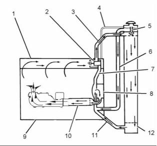
g01096647
Illustration 16
Cooling system for a warm engine
(1) Cylinder head
(2) Water temperature regulator
(3) Outlet pipe
(4) Vent line
The vent line is used to fill the cooling system with
coolant for the first time. This will purge any air out of
the top of a bottom filled system.
(5) Vent tube
(6) Shunt line
(7) Pipe
(8) Water pump
(9) Cylinder block
(10) Oil cooler
(11) Inlet pipe
i02550119
Basic Engine
(12) Radiator
In operation, the water pump (8) sends most of the
coolant from the radiator (12) to the oil cooler (10).
Cylinder Block Assembly
The coolant from the oil cooler (10) goes into the
cylinder block (9) through a bonnet and an elbow.
The coolant goes around the cylinder liners, through
the water directors and into the cylinder head.
Passages supply the lubrication for the crankshaft
bearings and the piston crowns. These passages
are cast into the cylinder block. Oil is supplied to the
passages by the cylinder block’s oil manifold.
The water directors send the flow of coolant around
the valves and the passages for exhaust gases in the
cylinder head. The coolant then goes to the front of
the cylinder head. At this point, water temperature
regulator (2) controls the direction of coolant flow.
The cylinder liner is an induction hardened liner. A
steel spacer plate provides improved reusability and
durability.
This document has been printed from SPI². Not for Resale
![]()
![]()
18
KENR6231
Systems Operation Section
Cylinder Head Assembly
Camshaft
The cylinder head is a one-piece cast iron head. The
cylinder head supports the camshaft. Steel reinforced
bearings are pressed into each bore. The bearings
are lubricated under pressure. Bridge dowels have
been eliminated as the valve train uses floating valve
bridges.
The camshaft has three lobes at each cylinder.
These lobes allow the camshaft to operate the unit
injector, the exhaust valves, and the inlet valves. The
camshaft is supported in the cylinder head by seven
journals which are fit with bearings. The camshaft
gear contains integral roller dampers that counteract
the torsional vibrations that are generated by the
high fuel pressure during fuel injector operation. The
design reduces gear train noise. The camshaft is
driven by an adjustable idler gear which is turned by
a fixed idler gear which is turned by a cluster idler
gear in the front gear train. Each bearing journal is
lubricated from the oil manifold in the cylinder head.
A thrust plate that is located at the front controls the
end play of the camshaft. Timing of the camshaft is
accomplished by aligning marks on the crankshaft
gear and idler gear, and camshaft gear with a mark
on the front timing plate.
Thermal efficiency is enhanced by the use of
stainless steel thermal sleeves in each exhaust port.
The sleeves reduce the amount of heat rejection to
the cooling system. The sleeves then transfer the
thermal energy to the turbocharger.
The unit injector is mounted in a stainless steel
adapter. This adapter has been pressed into the
cylinder head injector bore.
Pistons, Rings And Connecting
Rods
i02554889
The piston is a one-piece steel design that is retained
by the piston pin to the small end of the connecting
rod. The pistons have three rings that are located
in grooves in the steel crown. These rings seal the
combustion gas. The rings provide control of the oil.
The top ring has a barrel face. The second ring has
a tapered face and the ring has a coating of chrome
finish for the face. The third ring is the oil ring. The
third ring has a coil spring expander.
Electrical System
Grounding Practices
Proper grounding for the machine electrical system
and engine electrical systems is necessary for
proper machine performance and reliability. Improper
grounding will result in uncontrolled electrical circuit
paths and unreliable electrical circuit paths.
The connecting rod is a conventional design. The
cap of the connecting rod is attached to the shank by
two bolts that are threaded into the shank. Each side
of the small end of the connecting rod is machined
at an angle of 12 degrees in order to fit within the
piston cavity.
Uncontrolled engine electrical circuit paths can result
in damage to main bearings, crankshaft bearing
journal surfaces, and aluminum components.
To ensure proper functioning of the vehicle and
engine electrical systems, an engine-to-frame ground
strap with a direct path to the negative battery post
must be used. This may be provided by way of a
starting motor ground, a frame to starting motor
ground, or a direct frame to engine ground.
Crankshaft
The crankshaft converts the combustion force in the
cylinder into rotating torque. A vibration damper is
used at the front of the crankshaft in order to reduce
the torsional vibrations.
An engine-to-frame ground strap must be used in
order to connect the grounding stud of the engine to
the frame of the vehicle and to the negative battery
post.
The crankshaft drives a group of gears (front gear
train) on the front of the engine. The front gear
train provides power for the following components:
camshaft, water pump, oil pump, fuel transfer
pump, and accessory items that are specific to the
application.
The cylinder block has seven main bearings that
support the crankshaft. The cyl, inder block uses two
bolts to hold each of the bearing caps to the block.
The crankcase uses a lip seal at both ends of the
crankshaft.
This document has been printed from SPI². Not for Resale
![]()
KENR6231
19
Systems Operation Section
NOTICE
When boost starting an engine, the instructions in Op-
eration and Maintenance Manual, “Engine Starting”
should be followed in order to properly start the en-
gine.
This engine is equipped with a 24 volt starting system.
Only equal voltage for boost starting should be used.
The use of a higher voltage will damage the electrical
system.
The Electronic Control Module (ECM) must be dis-
connected at the “J1/P1” and “J2/P2” locations before
welding on the vehicle.
The engine has several input components which are
electronic. These components require an operating
voltage.
Unlike many electronic systems of the past, this
engine is tolerant to common external sources of
electrical noise. Buzzers that use electrical energy
can cause disruptions in the power supply. If buzzers
are used anywhere on the machine, the engine
electronics should be powered directly from the
battery system through a dedicated relay. The engine
electronics should not be powered through a common
power bus with other keyswitch activated devices.
g01028488
Illustration 17
Typical example
Grounding Stud To Battery Ground (“-”)
Engine Electrical System
The electrical system has the following separate
circuits:
• Charging
• Starting (If equipped)
• Accessories with low amperage
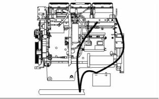
g01028479
Illustration 18
Typical example
Alternate Grounding Stud To Battery Ground (“-”)
The charging circuit is in operation when the engine
is running. An alternator makes electricity for the
charging circuit. A voltage regulator in the circuit
controls the electrical output in order to keep the
battery at full charge.
The engine must have a wire ground to the battery.
Ground wires or ground straps should be combined
at ground studs that are only for ground use. All of
the grounds should be tight and free of corrosion.
The starting circuit is activated only when the start
switch is activated.
All of the ground paths must be capable of carrying
any likely current faults. An AWG #0 or larger wire is
recommended for the grounding strap to the cylinder
head.
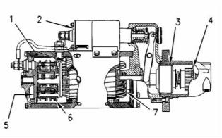
Charging System Components
Alternator
The engine alternator should be battery ground
with a wire size that is capable of managing the full
charging current of the alternator.
The alternator is driven by a belt from the crankshaft
pulley. This alternator is a three-phase, self-rectifying
charging unit, and the regulator is part of the
alternator.
This document has been printed from SPI². Not for Resale
![]()
![]()
![]()
![]()
![]()
20
KENR6231
Systems Operation Section
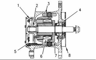
The alternator design has no need for slip rings
and the only part that has movement is the rotor
assembly. All conductors that carry current are
stationary. The following conductors are in the circuit:
• Field winding
• Stator windings
• Six rectifying diodes
• Regulator circuit components
The rotor assembly has many magnetic poles that
look like fingers with air space between each of the
opposite poles. The poles have residual magnetism.
The residual magnetism produces a small magnetic
field between the poles. As the rotor assembly
begins to turn between the field winding and the
stator windings, a small amount of alternating current
(AC) is produced. The AC current is produced in the
stator windings from the small magnetic field. The
AC current is changed to direct current (DC) when
the AC current passes through the diodes of the
rectifier bridge. The current is used for the following
applications:
g00425518
Illustration 19
Typical alternator components
(1) Regulator
(2) Roller bearing
(3) Stator winding
(4) Ball bearing
(5) Rectifier bridge
(6) Field winding
(7) Rotor assembly
(8) Fan
Starting System Components
• Charging the battery
Starting Solenoid
• Supplying the accessory circuit that has the low
amperage
• Strengthening the magnetic field
The first two applications use the majority of the
current. As the DC current increases through the
field windings, the strength of the magnetic field is
increased. As the magnetic field becomes stronger,
more AC current is produced in the stator windings.
The increased speed of the rotor assembly also
increases the current and voltage output of the
alternator.
The voltage regulator is a solid-state electronic
switch. The voltage regulator senses the voltage in
the system. The voltage regulator switches ON and
OFF many times per second in order to control the
field current for the alternator. The alternator uses
the field current in order to generate the required
voltage output.
g00317613
Illustration 20
Typical starting solenoid
NOTICE
Never operate the alternator without the battery in the
circuit. Making or breaking an alternator connection
with heavy load on the circuit can cause damage to
the regulator.
This document has been printed from SPI². Not for Resale
![]()
![]()
![]()
![]()
![]()
KENR6231
21
Systems Operation Section
When two sets of solenoid windings are used, the
windings are called the hold-in winding and the
pull-in winding. Both sets of windings have the same
number of turns around the cylinder, but the pull-in
winding uses a wire with a larger diameter. The wire
with a larger diameter produces a greater magnetic
field (1). When the start switch is closed, part of the
current flows from the battery through the hold-in
windings. The rest of the current flows through the
pull-in windings to the motor terminal. The current
then flows through the motor to ground. Solenoid
(2)is fully activated when the connection across the
battery and the motor terminal is complete. When
solenoid (2) is fully activated, the current is shut
off through the pull-in windings. At this point, only
the smaller hold-in windings are in operation. The
hold-in windings operate for the duration of time that
is required in order to start the engine. Solenoid (2)
will now draw less current from the battery, and the
heat that is generated by solenoid (2) will be kept at
an acceptable level.
g00425521
Illustration 21
Typical starting motor components
(1) Field
(2) Solenoid
(3) Clutch
(4) Pinion
(5) Commutator
(6) Brush assembly
(7) Armature
The starting solenoid (2) is an electromagnetic switch
that performs the following basic operations:
• The starting solenoid (2) closes the high current
starting motor circuit with a low current start switch
circuit.
• The starting solenoid (2) engages the pinion of the
starting motor (4) with the ring gear.
Solenoid (2) has windings (one or two sets) around
a hollow cylinder. A plunger that is spring loaded is
inside the cylinder. The plunger can move forward
and backward. When the start switch is closed and
electricity is sent through the windings, a magnetic
field (1) is made. The magnetic field (1) pulls the
plunger forward in the cylinder. This moves the shift
lever in order to engage the pinion drive gear with the
ring gear. The front end of the plunger then makes
contact across the battery and motor terminals of
solenoid (2). Next, the starting motor begins to turn
the flywheel of the engine.
When the start switch is opened, current no longer
flows through the windings. The spring now pushes
the plunger back to the original position. At the same
time, the spring moves the pinion gear away from
the flywheel.
This document has been printed from SPI². Not for Resale
![]()
![]()
22
KENR6231
Testing and Adjusting Section
Testing and Adjusting
Section
Testing and Adjusting
i02555248
Belt Tension Chart
Table 1
Required Tools
Tool
Part Number
Part Description
Qty
A
-
Belt Tension Gauge
1
Table 2
Fan Drive Belt Tension Chart
Initial Belt Tension
Gauge Reading
Size of Belt
Width of Belt
(1)
Used Belt Tension
(2)
800 N (180 lb)
5/8
15.875 mm (0.6250 inch)
868 N (195 lb)
Measure the tension of the belt that is farthest from the engine.
(1) Initial Belt Tension refers to a new belt.
(2) Used Belt Tension refers to a belt that has been in operation for 30 minutes or more at the rated speed.
Install Tooling (A) at the center of the longest free
length of belt and check the tension on the belt.
Check and adjust the tension on the tightest belt.
To adjust the belt tension, refer to Disassembly and
Assembly, “Belt Tightener - Install”.
Note: When the belts are replaced, always replace
the belts as a set.
Table 3
Alternator Belt Tension Chart
Gauge Reading
Used Belt Tension
(2)
267 N (60.0243 lb)
Size of Belt
Width of Belt
Initial Belt Tension
(1)
3/8
9.525 mm (0.3750 inch)
400 N (89.9240 lb)
Measure the tension of the belt that is farthest from the engine.
(1) Initial Belt Tension refers to a new belt.
(2) Used Belt Tension refers to a belt that has been in operation for 30 minutes or more at the rated speed.
Install Tooling (A) at the center of the longest free
length of belt and check the tension on the belt.
Check and adjust the tension on the tightest belt.
To adjust the belt tension, refer to Disassembly and
Assembly, “Alternator - Install”.
This document has been printed from SPI². Not for Resale
![]()
KENR6231
23
Testing and Adjusting Section
Fuel System
Fuel System - Inspect
• Relief valves
• Check valves
i02550123
Observe the fuel flow during engine cranking.
Look for air bubbles in the fuel. If there is no fuel
in the sight gauge, prime the fuel system. Refer to
System Operation, Testing and Adjusting, “Fuel
System - Prime” for more information. If the engine
starts, check for air in the fuel at varying engine
speeds. When possible, operate the engine under
the conditions which have been suspect of air in
the fuel.
A problem with the components that send fuel to
the engine can cause low fuel pressure. This can
decrease engine performance.
1. Check the fuel level in the fuel tank. Ensure that
the vent in the fuel cap is not filled with dirt.
2. Check all fuel lines for fuel leakage. The fuel lines
must be free from restrictions and faulty bends.
Verify that the fuel return line is not collapsed.
3. Install a new fuel filter.
4. Cut the old filter open with a suitable filter cutter.
Inspect the filter for excess contamination.
Determine the source of the contamination. Make
the necessary repairs.
5. Service the primary fuel filter (if equipped).
6. Operate the hand priming pump (if equipped).
If excessive resistance is felt, inspect the fuel
pressure regulating valve. If uneven resistance
is felt, test for air in the fuel. Refer to Systems
Operation, Testing and Adjusting, “Air in Fuel -
Test” for more information.
g01096678
Illustration 22
7. Remove any air that may be in the fuel system.
Refer to Systems Operation, Testing and
Adjusting, “Fuel System - Prime”.
(1) A steady stream of small bubbles with a diameter of
approximately 1.60 mm (0.063 inch) is an acceptable amount
of air in the fuel.
(2) Bubbles with a diameter of approximately 6.35 mm (0.250 inch)
are also acceptable if there is two seconds to three seconds
intervals between bubbles.
(3) Excessive air bubbles in the fuel are not acceptable.
i02550146
Air in Fuel - Test
3. If excessive air is seen in the sight gauge in the
fuel return line, install a second sight gauge at the
inlet to the fuel transfer pump. If a second sight
gauge is not available, move the sight gauge from
the fuel return line and install the sight gauge
at the inlet to the fuel transfer pump. Observe
the fuel flow during engine cranking. Look for air
bubbles in the fuel. If the engine starts, check for
air in the fuel at varying engine speeds.
This procedure checks for air in the fuel. This
procedure also assists in finding the source of the air.
1. Examine the fuel system for leaks. Ensure that
the fuel line fittings are properly tightened. Check
the fuel level in the fuel tank. Air can enter the
fuel system on the suction side between the fuel
transfer pump and the fuel tank.
If excessive air is not seen at the inlet to the fuel
transfer pump, the air is entering the system after
the fuel transfer pump. Proceed to Step 6.
2. Install a suitable fuel flow tube with a visual sight
gauge in the fuel return line. When possible, install
the sight gauge in a straight section of the fuel line
that is at least 304.8 mm (12 inches) long. Do not
install the sight gauge near the following devices
that create turbulence:
If excessive air is seen at the inlet to the fuel
transfer pump, air is entering through the suction
side of the fuel system.
• Elbows
This document has been printed from SPI². Not for Resale
免費(fèi)熱線
400-100-8969???15088860848
400-100-8969???15088860848
機(jī)組銷售
0574-26871589? 15267810868
0574-26871589? 15267810868
配件銷售
0574-26886646? 15706865167
0574-26886646? 15706865167
維修熱線
0574-26871569 18658287286
0574-26871569 18658287286
手機(jī)端

微信公眾號(hào)
在線客服