 English
 Espaol
 Franais
 阿拉伯
阿拉伯 中文(簡)
中文(簡) Deutsch
 Italiano
 Português
 日本
日本 韓國
韓國 български
 hrvatski
 esky
esky Dansk
Dansk Nederlands
 suomi
suomi Ελληνικ
 印度
印度 norsk
norsk Polski
 Roman
Roman русский
 Svenska
 珀金斯Perkins2506-15發(fā)動機(jī)拆卸組裝手冊,珀金斯Perkins2506-15發(fā)動機(jī)拆卸組裝手冊技術(shù)支持中心,珀金斯Perkins2506-15發(fā)動機(jī)拆卸組裝手冊代理商,珀金斯Perkins2506-15發(fā)動機(jī)拆卸組裝手冊銷售服務(wù)中心,珀金斯Perkins2506-15發(fā)動機(jī)拆卸組裝手冊價(jià)格規(guī)格資料查詢,寧波日昕動力科技有限公司

首頁
產(chǎn)品展示>珀金斯Perkins2506-15發(fā)動機(jī)拆卸組裝手冊
珀金斯Perkins2506-15發(fā)動機(jī)拆卸組裝手冊
詳細(xì)描述
Disassembly and
Assembly
2506-15 Industrial Engine
M G A (Engine)
MGB (Engine)
M G D (Engine)
Table of Contents
Cylinder Head - Remove ...................................... 51
Cylinder Head - Install .......................................... 53
Camshaft - Remove .............................................. 56
Camshaft - Install .................................................. 58
Camshaft Gear - Remove and Install .................. 60
Camshaft Bearings - Remove ............................... 61
Camshaft Bearings - Install ................................... 62
Engine Oil Pan - Remove and Install ................... 64
Cylinder Liner - Remove ....................................... 65
Cylinder Liner - Install ........................................... 66
Piston Cooling Jets - Remove and Install ............. 66
Pistons and Connecting Rods - Remove .............. 67
Pistons and Connecting Rods - Disassemble ....... 68
Pistons and Connecting Rods - Assemble ........... 69
Pistons and Connecting Rods - Install .................. 70
Connecting Rod Bearings - Remove (Connecting
rods in position) ................................................... 71
Connecting Rod Bearings - Install (Connecting rods
in position) ........................................................... 71
Crankshaft Main Bearings - Remove .................... 73
Crankshaft Main Bearings - Install ........................ 74
Crankshaft - Remove ............................................ 75
Crankshaft - Install ................................................ 77
Bearing Clearance - Check ................................... 79
Atmospheric Pressure Sensor - Remove and
Disassembly and Assembly Section
Fuel Priming Pump - Remove and Install ............ 4
Fuel Filter Base - Remove ................................... 4
Fuel Filter Base - Disassemble ............................. 5
Fuel Filter Base - Assemble .................................. 6
Fuel Filter Base - Install ....................................... 6
Fuel Transfer Pump - Remove .............................. 7
Fuel Transfer Pump - Install .................................. 7
Electronic Unit Injector - Remove ......................... 8
Electronic Unit Injector - Install ............................. 9
Electronic Unit Injector Sleeve - Remove ............. 10
Electronic Unit Injector Sleeve - Install ................. 11
Turbocharger - Remove ........................................ 12
Turbocharger - Install ............................................ 13
Exhaust Manifold - Remove and Install ............... 14
Exhaust Elbow - Remove and Install ................... 15
Inlet and Exhaust Valve Springs - Remove and
Install ................................................................... 15
Inlet and Exhaust Valves - Remove and Install .... 17
Inlet and Exhaust Valve Guides - Remove and
Install ................................................................... 19
Engine Oil Filter Base - Remove .......................... 20
Engine Oil Filter Base - Disassemble ................... 21
Engine Oil Filter Base - Assemble ........................ 21
Engine Oil Filter Base - Install .............................. 22
Engine Oil Cooler - Remove ................................. 23
Engine Oil Cooler - Install ..................................... 23
Engine Oil Pump - Remove .................................. 24
Engine Oil Pump - Disassemble ........................... 24
Engine Oil Pump - Assemble ................................ 25
Engine Oil Pump - Install ...................................... 26
Water Pump - Remove ......................................... 27
Water Pump - Install ............................................. 28
Water Temperature Regulator Housing - Remove and
Install .................................................................. 28
Engine Support (Front) - Remove and Install ....... 30
Flywheel - Remove ............................................... 31
Flywheel - Install ................................................... 32
Crankshaft Rear Seal - Remove ........................... 33
Crankshaft Rear Seal - Install ............................... 34
Flywheel Housing - Remove and Install .............. 34
Vibration Damper and Pulley - Remove and Install
............................................................................. 36
Crankshaft Front Seal - Remove .......................... 38
Crankshaft Front Seal - Install .............................. 39
Front Cover - Remove .......................................... 40
Front Cover - Install .............................................. 41
Gear Group (Front) - Remove .............................. 41
Gear Group (Front) - Install .................................. 43
Housing (Front) - Remove .................................... 45
Housing (Front) - Install ........................................ 46
Crankcase Breather - Remove and Install (Open
Breather) ............................................................. 47
Valve Mechanism Cover - Remove and Install ..... 48
Rocker Arm and Shaft - Remove .......................... 49
Rocker Arm - Disassemble ................................... 49
Rocker Arm - Assemble ........................................ 50
Rocker Arm and Shaft - Install .............................. 51
Install ................................................................... 80
Camshaft Position Sensor - Remove and Install .. 81
Crankshaft Position Sensor - Remove and
Install ................................................................... 82
Coolant Temperature Sensor - Remove and
Install ................................................................... 83
Engine Oil Pressure Sensor - Remove and Install
............................................................................. 84
Fuel Temperature Sensor - Remove and Install ... 85
Inlet Manifold Temperature Sensor - Remove and
Install ................................................................... 86
Inlet Manifold Pressure Sensor - Remove and
Install ................................................................... 87
Belt Tightener - Remove ....................................... 88
Belt Tightener - Install ........................................... 89
Fan - Remove and Install ..................................... 89
Fan Drive - Remove ............................................. 90
Fan Drive - Install .................................................. 91
Pump Drive - Remove (Transfer pump) ................ 91
Pump Drive - Disassemble (Transfer pump) ......... 92
Pump Drive - Assemble (Transfer pump) ............. 93
Pump Drive - Install (Transfer pump) .................... 93
Electronic Control Module - Remove and Install ... 94
Alternator - Remove and Install ........................... 95
Electric Starting Motor - Remove and Install ....... 96
Index Section
Index ..................................................................... 97
This document has been printed from SPI². Not for Resale
![]()
4
KENR6232
Disassembly and Assembly Section
Disassembly and Assembly
Section
Installation Procedure
NOTICE
Keep all parts clean from contaminants.
i02554756
Fuel Priming Pump - Remove
and Install
Contaminants may cause rapid wear and shortened
component life.
Removal Procedure
NOTICE
Care must be taken to ensure that fluids are contained
during performance of inspection, maintenance, test-
ing, adjusting and repair of the product. Be prepared to
collect the fluid with suitable containers before open-
ing any compartment or disassembling any compo-
nent containing fluids.
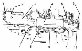
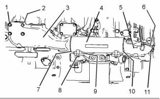
g01279497
Dispose of all fluids according to local regulations and
mandates.
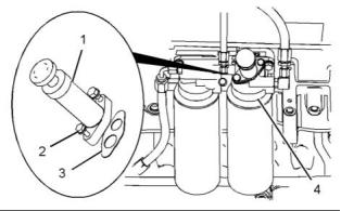
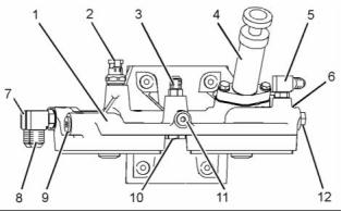
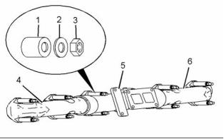
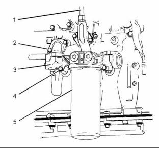
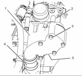
Illustration 2
1. Position a new joint (3) on fuel filter base (4).
Note: Ensure correct orientation of the joint.
NOTICE
Keep all parts clean from contaminants.
2. Position the fuel priming pump assembly (1) on
the fuel filter base and install bolts (2). Tighten the
1/4" bolt to a torque of 12 N·m (105 lb in). Tighten
the 5/16" bolt to a torque of 25 N·m (221 lb in).
Contaminants may cause rapid wear and shortened
component life.
1. Turn the fuel supply to the “OFF” position.
3. Turn the fuel supply to the “ON” position.
4. Remove the air from the system. Refer to Systems
Operation, Testing and Adjusting, “Fuel System -
Prime”.
i02554755
Fuel Filter Base - Remove
Removal Procedure
NOTICE
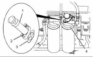
g01279497
Illustration 1
Care must be taken to ensure that fluids are contained
during performance of inspection, maintenance, test-
ing, adjusting and repair of the product. Be prepared to
collect the fluid with suitable containers before open-
ing any compartment or disassembling any compo-
nent containing fluids.
2. Remove bolts (2). Remove fuel priming pump
assembly (1) from fuel filter base (4).
3. Remove joint (3) from the fuel priming pump
assembly and the fuel filter base.
Dispose of all fluids according to local regulations and
mandates.
This document has been printed from SPI². Not for Resale
![]()
![]()
![]()
![]()
![]()
![]()
![]()
![]()
![]()
![]()
![]()
KENR6232
5
Disassembly and Assembly Section
i02554753
Fuel Filter Base - Disassemble
NOTICE
Keep all parts clean from contaminants.
Contaminants may cause rapid wear and shortened
component life.
Disassembly Procedure
1. Turn the fuel supply to the “OFF” position.
Start By:
a. Remove the fuel filter base. Refer to Disassembly
and Assembly, “Fuel Filter Base - Remove”.
NOTICE
Keep all parts clean from contaminants.
Contaminants may cause rapid wear and shortened
component life.
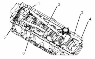
g01279811
Illustration 3
2. Place a suitable container below the fuel filter
base in order to drain the fuel from the fuel filter
assemblies (10) and (12).
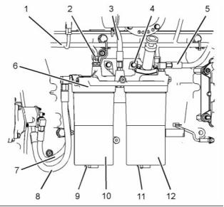
g01279898
Illustration 4
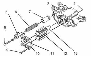
1. Remove fuel priming pump (4) from fuel filter
base assembly (1). Refer to Disassembly and
Assembly, “Fuel Priming Pump - Remove and
Install”.
3. Remove plugs (9) and (11). Allow the fuel to drain.
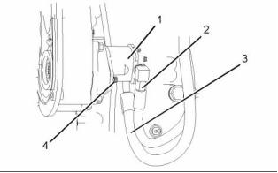
4. Disconnect harness assembly (1) from fuel
temperature sensor (2).
2. Remove fuel temperature sensor (2) from fuel
filter base assembly (1). Refer to Disassembly and
Assembly, “Fuel Temperature Sensor - Remove
and Install”.
Note: In order to disconnect the harness assembly,
slide the locking tab into the unlocked position.
5. Disconnect hose assembly (3). Disconnect hose
assembly (5). Disconnect hose assemblies (7)
and (8). Plug the open hose assemblies.
3. Remove fuel bypass valve (6) from fuel filter base
assembly (1). Remove the O-ring seals from the
fuel bypass valve.
6. Use a suitable tool with a 1/2" square drive
in order to remove fuel filter assemblies (10)
and (12). Remove the O-ring seals. Remove
the fuel filter elements. Refer to Operation and
Maintenance Manual, “Fuel Filter - Replace” for
more information.
4. Remove fuel check valve (10) from fuel filter base
assembly (1). Remove the O-ring seals from the
fuel check valve.
5. Remove connections (3), (5), (7) and (8) from fuel
filter base assembly (1). Remove the O-ring seals
from the connections.
7. Remove bolts (4). Remove fuel filter base (6).
6. Remove plugs (9), (11) and (12) from fuel filter
base assembly (1). Remove the O-ring seals from
the plugs.
This document has been printed from SPI². Not for Resale
![]()
![]()
![]()
![]()
![]()
![]()
![]()

6
KENR6232
Disassembly and Assembly Section
i02554752
Fuel Filter Base - Assemble
6. Install fuel temperature sensor (2) to fuel filter
base assembly (1). Refer to Disassembly and
Assembly, “Fuel Temperature Sensor - Remove
and Install”.
7. Install fuel priming pump (4) to fuel filter
base assembly (1). Refer to Disassembly and
Assembly, “Fuel Priming Pump - Remove and
Install”.
Assembly Procedure
NOTICE
Keep all parts clean from contaminants.
End By:
Contaminants may cause rapid wear and shortened
component life.
a. Install the fuel filter base. Refer to Disassembly
and Assembly, “Fuel Filter Base - Install”.
1. Ensure that the filter base is clean and free from
i02554754
damage. If necessary, replace the filter base.
Fuel Filter Base - Install
Installation Procedure
NOTICE
Keep all parts clean from contaminants.
Contaminants may cause rapid wear and shortened
component life.
g01279898
Illustration 5
2. Install new O-ring seals to plugs (9), (11) and (12).
Install the plugs to fuel filter base assembly (1).
Tighten plug (9) to a torque of 41 N·m (30 lb ft).
Tighten plugs (11) and (12) to a torque of 15 N·m
(11 lb ft).
3. Install new O-ring seals to connections (3), (5), (7)
and (8). Install the connections to fuel filter base
assembly (1). Tighten connections (3), (5) and (7)
to a torque of 15 N·m (11 lb ft). Tighten connection
(8) to a torque of 41 N·m (30 lb ft).
Note: Ensure correct orientation of the connections.
4. Install new O-ring seals to fuel bypass valve (6).
Install the fuel bypass valve to fuel filter base
assembly (1). Tighten fuel bypass valve (6) to a
torque of 35 N·m (26 lb ft).
g01279811
Illustration 6
1. Position fuel filter base (6) and install bolts (4).
5. Install new O-ring seals to fuel check valve (10).
Install the fuel check valve in fuel filter base
assembly (1). Tighten the fuel check valve to a
torque of 35 N·m (26 lb ft).
Tighten the bolts to a torque of 47 N·m (35 lb ft).
2. Install new O-ring seals and new fuel filter
elements to fuel filter assemblies (10) and (12).
Use a suitable tool with a 1/2" square drive in
order to install the fuel filter assemblies.
This document has been printed from SPI². Not for Resale
![]()
![]()
![]()
![]()
![]()
![]()
![]()

KENR6232
7
Disassembly and Assembly Section
Install new O-ring seals to plugs (9) and (11).
Install the plugs to fuel filter assemblies (10) and
(12).
Refer to Operation and Maintenance Manual,
“Fuel Filter - Replace” for more information.
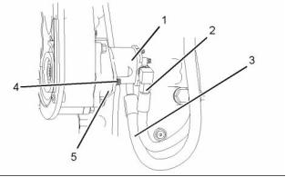
3. Connect hose assemblies (3), (5), (7) and (8).
4. Connect harness assembly (1) to fuel temperature
sensor (2). Slide the locking tab into the locked
position.
5. Turn the fuel supply to the “ON” position.
g01280901
6. Remove the air from the system. Refer to Systems
Operation, Testing and Adjusting, “Fuel System -
Prime”.
Illustration 7
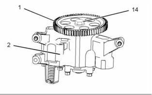
3. Disconnect hose assemblies (2) and (3) from fuel
transfer pump (1). Plug the open hose assemblies.
4. Remove bolts (4) and remove fuel transfer pump
i02554761
Fuel Transfer Pump - Remove
(1).
5. Remove the O-ring seal from fuel transfer pump
(1).
Removal Procedure
i02554849
NOTICE
Fuel Transfer Pump - Install
Care must be taken to ensure that fluids are contained
during performance of inspection, maintenance, test-
ing, adjusting and repair of the product. Be prepared to
collect the fluid with suitable containers before open-
ing any compartment or disassembling any compo-
nent containing fluids.
Installation Procedure
NOTICE
Keep all parts clean from contaminants.
Dispose of all fluids according to local regulations and
mandates.
Contaminants may cause rapid wear and shortened
component life.
NOTICE
Keep all parts clean from contaminants.
1. Ensure that the fuel transfer pump is clean and
free from damage.
Contaminants may cause rapid wear and shortened
component life.
1. Turn the fuel supply to the “OFF” position.
2. Place a suitable container below the fuel transfer
pump in order to catch any fuel that might be
spilled.
g01280943
Illustration 8
2. Lubricate a new O-ring seal with clean engine oil.
Install the O-ring seal to fuel transfer pump (1).
This document has been printed from SPI². Not for Resale
![]()
![]()
![]()
![]()
![]()
![]()
![]()
![]()
![]()
8
KENR6232
Disassembly and Assembly Section
3. Position fuel transfer pump (1) on pump drive (5).
Note: Ensure that the splines on the shaft of the fuel
transfer pump are correctly engaged into the pump
drive.
4. Install bolts (4). Tighten the bolts to a torque of
47 N·m (35 lb ft).
5. Remove the plugs from the hose assemblies.
Connect hose assemblies (2) and (3) to fuel
transfer pump (1).
6. Turn the fuel supply to the “ON” position.
g01150587
7. Remove the air from the fuel system. Refer to
Systems Operation, Testing and Adjusting, “Fuel
System - Prime”.
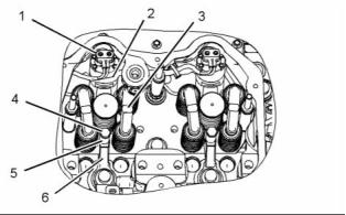
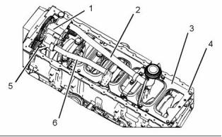
Illustration 9
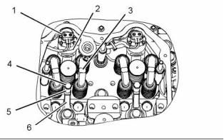
2. Disconnect harness assembly (1) from electronic
unit injector (2).
3. Remove valve bridges (3).
i02554720
Electronic Unit Injector -
Remove
NOTICE
If the injector hold down bolt is loose during the re-
moval procedure, inspect the injector bore for wear
and debris. Replace the clamp and spacer.
Removal Procedure
Table 1
Required Tools
Tool
Part Number
Part Description
Pry Bar
Qty
A
27610288
1
Start By:
a. Remove the rocker arms and the rocker arm shaft.
Refer to Disassembly and Assembly, “Rocker Arm
and Shaft - Remove”.
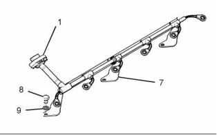
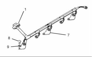
g01284035
Illustration 10
NOTICE
Keep all parts clean from contaminants.
4. Remove bolts (8) and washers (9). Remove
harness assembly (1) and support bracket (7) as
a unit.
Contaminants may cause rapid wear and shortened
component life.
5. Remove bolt (4) and spacer (5).
1. Turn the fuel supply to the OFF position.
6. Place an identification mark on electronic unit
injector (2) for installation purposes. Each
electronic unit injector must be reinstalled in the
original location in the cylinder head.
This document has been printed from SPI². Not for Resale
![]()
![]()
![]()
![]()
![]()
![]()
![]()
KENR6232
9
Disassembly and Assembly Section
i02554719
Electronic Unit Injector - Install
Installation Procedure
Table 2
Required Tools
Tool
Part
Part Description
Qty
Number
GE50028
GE50046
Vacuum Pump
1
1
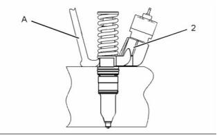
g01073439
Illustration 11
Fluid Sampling Bottle
B
Tube
7. Use Tooling (A) to pry beneath the base and free
GE50030
-
1
1
1
1
7.9 mm (0.31 inch) OD
electronic unit injector (2).
C
D
E
Large Bore Brush
8. Remove electronic unit injector (2) and clamp (6)
Surface Reconditioning
Pad
from the cylinder head.
27610308
27610296
Torque Wrench
NOTICE
Keep all parts clean from contaminants.
Contaminants may cause rapid wear and shortened
component life.
1. Use Tooling (D) to clean the carbon deposit from
the inside of the electronic unit injector sleeve.
2. Use Tooling (B) to remove the fuel and oil from
the cylinder. Evacuate as much fuel and oil as
possible from the cylinder before installing the
electronic unit injector. Several evacuations may
be necessary.
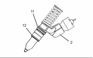
g01284341
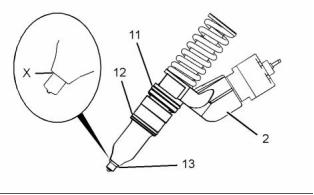
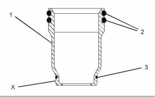
Illustration 12
9. Remove O-ring seals (11) and (12) from electronic
unit injector (2).
g01284074
Illustration 13
3. Ensure that seat area (X) on the electronic unit
injector is clean and free carbon.
4. Install new O-ring seals (11) and (12) on the
electronic unit injector. Lubricate the O-ring seals
with clean engine oil.
This document has been printed from SPI². Not for Resale
![]()
![]()
![]()

![]()
![]()
![]()
10
KENR6232
Disassembly and Assembly Section
5. Install a new O-ring seal (13) on the electronic unit
Note: Ensure that used valve bridges are reinstalled
in the original location and the original orientation.
Do not interchange the location or the orientation of
used valve bridges.
injector.
Note: O-ring seal (13) should be installed dry.
11. Install the rocker arms and the rocker arm shaft.
Refer to Disassembly and Assembly, “Rocker Arm
and Shaft - Install”.
NOTICE
If a replacement electronic unit injector is installed, the
calibration code must be programmed into the elec-
tronic control module. Refer to Troubleshooting Guide,
“Injector Trim File” for more information.
12. Turn the fuel supply to the “ON” position.
13. Remove the air from the fuel system. Refer to
Systems Operation, Testing and Adjusting, “Fuel
System - Prime”.
i02554722
Electronic Unit Injector Sleeve
- Remove
Removal Procedure
Table 3
g01150587
Illustration 14
Required Tools
6. Install clamp (6) to electronic unit injector (2).
Install electronic unit injector (2) into the original
location in the cylinder head.
Tool
Part Number
Part Description
Qty
A
GE50021
Injector Sleeve Tool
1
7. Install spacer (5) and bolt (4). Tighten bolt (4) to a
Start By:
torque of 55 N·m (41 lb ft).
a. Remove the electronic unit injectors. Refer to
Disassembly and Assembly, “Electronic Unit
Injector - Remove”.
NOTICE
Keep all parts clean from contaminants.
Contaminants may cause rapid wear and shortened
component life.
1. Drain the coolant from the engine. Refer to
Operation and Maintenance Manual, “Cooling
System Coolant - Change”.
g01284035
Illustration 15
8. Install harness assembly (1) and support bracket
(7) as a unit. Install bolts (8) and washers (9).
Tighten bolts (8) to a torque of 105 N·m (77 lb ft).
9. Connect harness assembly (1) to electronic unit
injector (2). Use Tooling (E) to tighten the nuts to a
torque of 2.5 N·m (22 lb in).
10. Install bridge assemblies (3) in the respective
locations.
This document has been printed from SPI². Not for Resale
![]()
![]()
![]()
![]()
![]()

![]()
![]()
KENR6232
11
Disassembly and Assembly Section
NOTICE
Ensure that the electronic unit injector sleeve and the
cylinder head bore are completely free of oil, dirt, and
sealant debris.
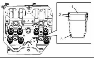
g01076133
Illustration 16
2. Install Tooling (A) in electronic unit injector sleeve
(1).
3. Tighten the nut on Tooling (A) until the electronic
unit injector sleeve is pulled free of the cylinder
head.
g01043165
Illustration 17
2. Install new O-ring seals (2) and (3) to electronic
unit injector sleeve (1).
4. Remove O-ring seals (2) and O-ring seal (3) from
electronic unit injector sleeve (1).
Note: Do not apply Tooling (C) to the cylinder head
surfaces. Apply Tooling (C) to the electronic unit
injector sleeve only.
i02554721
Electronic Unit Injector Sleeve
- Install
3. Apply a small continuous bead of Tooling (C) to
surface (X) of electronic unit injector sleeve (1).
4. Lubricate O-ring seals (2) with clean engine oil.
5. Position Tooling (A) and the electronic unit injector
sleeve in the cylinder head. Use care not to
damage the O-ring seals on the electronic unit
injector sleeve.
Installation Procedure
Table 4
Required Tools
6. Use Tooling (A) to install electronic unit injector
Tool
Part Number
GE50021
GE50023
GE50024
GE50022
CV60893
Part Description
Injector Sleeve Tool
Tapered Brush
Qty
1
sleeve (1) in the cylinder head.
A
Note: Ensure that the electronic unit injector sleeve
1
is properly seated in the cylinder head.
B
C
Small Bore Brush
End Brush
1
7. Remove Tooling (A). Use a clean towel and
1
remove excess Tooling (C).
Retaining Compound
1
8. Fill the cooling system with coolant. Refer to
Operation and Maintenance, “Refill Capacities” for
the cooling system capacity.
NOTICE
Keep all parts clean from contaminants.
End By:
Contaminants may cause rapid wear and shortened
component life.
a. Install the electronic unit injectors. Refer to
Disassembly and Assembly, “Electronic Unit
Injector - Install”.
1. Use Tooling (B) to clean the bore in the cylinder
head for the electronic unit injector sleeve.
This document has been printed from SPI². Not for Resale
![]()
![]()
![]()
![]()
![]()
![]()
![]()
12
KENR6232
Disassembly and Assembly Section
i02554785
Turbocharger - Remove
Removal Procedure
Start By:
a. Remove the exhaust elbow. Refer to Disassembly
and Assembly, “Exhaust Elbow - Remove and
Install”.
NOTICE
Care must be taken to ensure that fluids are contained
during performance of inspection, maintenance, test-
ing, adjusting and repair of the product. Be prepared to
collect the fluid with suitable containers before open-
ing any compartment or disassembling any compo-
nent containing fluids.
Dispose of all fluids according to local regulations and
mandates.
NOTICE
Keep all parts clean from contaminants.
Contaminants may cause rapid wear and shortened
component life.
1. Disconnect the air hoses for the turbocharger inlet
and for the turbocharger outlet.
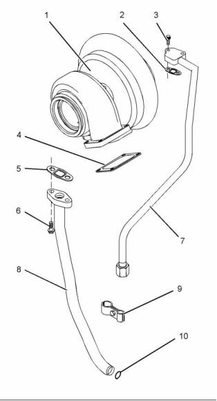
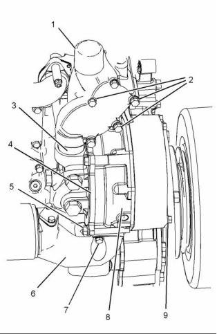
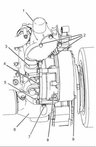
g01283022
Illustration 18
2. Follow Steps 2.a through 2.c in order to remove
the tube assembly (7) for the oil feed.
a. Remove tube clamp (9) that secures tube
assembly (7) to tube assembly (8). Note the
position of the clamp.
b. Disconnect tube assembly (7) from the engine
oil filter base.
c. Remove bolts (3). Remove tube assembly (7)
and joint (2) from turbocharger (1).
3. Follow Steps 3 through 3.c in order to remove the
tube assembly (8) for the oil drain.
a. Remove bolts (6).
This document has been printed from SPI². Not for Resale
![]()
![]()
![]()
![]()
![]()
![]()

KENR6232
13
Disassembly and Assembly Section
b. Remove tube assembly (8) and joint (5).
c. Remove O-ring seal (10) from tube assembly
(8).
4. Attach a suitable lifting device to turbocharger (1).
The weight of the turbocharger is approximately
30 kg (66 lb).
5. Remove the fasteners for the turbocharger. Use
the lifting device to remove turbocharger (1) from
the exhaust manifold. Remove gasket (4).
i02554784
Turbocharger - Install
Installation Procedure
Table 5
Required Tools
Tool
Part
Part Description
Qty
Number
A
CV60889
Anti-Seize Compound
1
NOTICE
Keep all parts clean from contaminants.
Contaminants may cause rapid wear and shortened
component life.
g01283022
Illustration 19
1. Clean the mating surfaces of the exhaust manifold.
Position a new gasket (4) on the exhaust manifold.
2. Attach a suitable lifting device to turbocharger
(1). The weight of turbocharger is approximately
30 kg (66 lb). Use the lifting device to install
turbocharger (1) onto the exhaust manifold.
3. Apply Tooling (A) to the threads of the exhaust
manifold bolts. Install the bolts and install locknuts
finger tight.
4. Install a new O-ring seal (10) to tube assembly
(8). Install tube assembly (7) and new joint (5).
Install bolts (6) finger tight.
5. Install tube assembly (7) and a new joint (2).
Install bolts (3) finger tight. Connect the lower end
of tube assembly (7) to the engine oil filter base.
This document has been printed from SPI². Not for Resale
![]()

![]()
![]()
![]()
14
KENR6232
Disassembly and Assembly Section
6. Install tube clamp (9) to tube assembly (7) to tube
5. If necessary, remove the taperlock studs from the
assembly (8).
cylinder head.
Note: Ensure that the clamp is installed in the correct
Installation Procedure
position.
Table 6
7. Tighten the fasteners for the turbocharger to a
Required Tools
torque of 55 N·m (41 lb ft).
Tool
Part Number
Part Description
Qty
-
8. Tighten the bolts for tube assemblies (7) and (8)
A
CV60889
Anti-Seize Compound
to a torque of 47 N·m (35 lb ft).
9. Connect the air hoses for the turbocharger inlet
NOTICE
and for the turbocharger outlet.
Keep all parts clean from contaminants.
Contaminants may cause rapid wear and shortened
component life.
i02554739
Exhaust Manifold - Remove
and Install
1. Install the taperlock studs in the cylinder head and
tighten to a torque of 35 N·m (26 lb ft).
Removal Procedure
Start By:
a. Remove the turbocharger. Refer to Disassembly
and Assembly, “Turbocharger - Remove”.
b. Remove the water temperature regulator housing.
Refer to Disassembly and Assembly, “Water
Temperature Regulator Housing - Remove and
Install”.
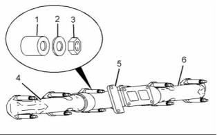
g01283599
Illustration 21
2. Assemble exhaust manifolds (4), (5) and (6).
3. Install the exhaust manifold gaskets onto the
taperlock studs.
4. Install the assembly of the exhaust manifolds on
the taperlock studs.
Note: Ensure that the holes in exhaust manifolds are
centralized with the taperlock studs.
g01283599
5. Apply Tooling (A) to the threads of the taperlock
studs. Install spacers (1), washers (2) and
locknuts (3).
Illustration 20
1. Remove locknuts (3), washers (2) and spacers (1).
2. Remove exhaust manifolds (4), (5) and (6).
Note: Remove manifolds as one assembly.
3. Remove the exhaust manifold gaskets.
4. Remove exhaust manifolds (4) and (6) from
exhaust manifold (5).
g01100255
Illustration 22
This document has been printed from SPI². Not for Resale
![]()
![]()

![]()
![]()
![]()
![]()
KENR6232
15
Disassembly and Assembly Section
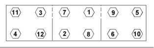
6. Tighten the locknuts in a numerical sequence that
is shown in Illustration 22. Tighten the locknuts to
a torque of 38 N·m (28 lb ft).
Installation Procedures
NOTICE
Keep all parts clean from contaminants.
End By:
Contaminants may cause rapid wear and shortened
component life.
a. Install the water temperature regulator housing.
Refer to Disassembly and Assembly, “Water
Temperature Regulator Housing - Remove and
Install”.
b. Install the turbocharger. Refer to Disassembly and
Assembly, “Turbocharger - Install”.
i02554738
Exhaust Elbow - Remove and
Install
Removal Procedure
NOTICE
Keep all parts clean from contaminants.
Contaminants may cause rapid wear and shortened
component life.
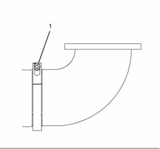
g01296103
Illustration 24
1. Thoroughly clean the exhaust elbow and the outlet
of the turbocharger. Inspect the components for
wear or damage. Replace any components that
are worn or damaged.
2. Position clamp (1) and install the exhaust elbow
to the turbocharger. Ensure correct orientation of
the band clamp.
3. Tighten the allen head bolt to a torque of 13.5 N·m
(10 lb ft).
i02554768
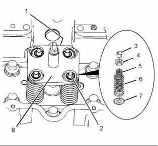
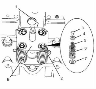
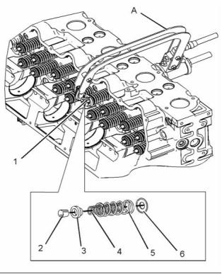
Inlet and Exhaust Valve
Springs - Remove and Install
Removal Procedure
g01296103
Illustration 23
1. Use an allen wrench in order to loosen clamp (1)
Table 7
that secures the exhaust elbow.
Required Tools
Tool
A
Part Number
CH11148
Part Description
Engine Turning Tool
Qty
1
2. Remove the exhaust elbow and the clamp from
the turbocharger.
B
GE50026
Valve Spring Compressor
1
This document has been printed from SPI². Not for Resale
![]()
![]()
![]()
![]()
![]()
![]()
![]()

16
KENR6232
Disassembly and Assembly Section
Start By:
a. Remove the electronic unit injectors. Refer to
Disassembly and Assembly, “Electronic Unit
Injector - Remove”.
NOTICE
Keep all parts clean from contaminants.
Contaminants may cause rapid wear and shortened
component life.
Note: The following procedure should be adopted in
order to remove the valve springs when the cylinder
head is installed to the engine. Refer to Disassembly
and Assembly Manual, “Inlet and Exhaust Valves -
Remove and Install” for the procedure to remove the
valve springs from a cylinder head that has been
removed from the engine.
1. Use Tooling (A) to position the appropriate piston
at the top center position before the valve spring
is removed.
g01284821
Illustration 26
Note: Failure to ensure that the piston is at the top
center position may allow the valve to drop into the
cylinder bore.
Personal injury can result from being struck by
parts propelled by a released spring force.
Make sure to wear all necessary protective equip-
ment.
NOTICE
Do not turn the crankshaft while the valve springs are
removed.
Follow the recommended procedure and use all
recommended tooling to release the spring force.
Note: Valve springs must be replaced in pairs for the
inlet valves or the exhaust valves of each cylinder. If
all valve springs require replacement the procedure
can be carried out on two cylinders at the same time.
The procedure can be carried out on the following
pairs of cylinders. 1 with 6, 2 with 5, and 3 with 4.
Ensure that all of the valve springs are installed
before changing from one pair of cylinders to another
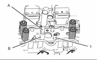
pair of cylinders.
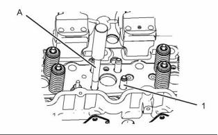
2. Install Tooling (B) in the electronic unit injector
sleeve. Secure Tooling (B) with unit injector clamp
(1).
3. Tighten the nut until valve keepers (3) are loose
on valves (2).
4. Remove valve keepers (3).
5. Loosen the nut in order to release the pressure
on Tooling (B). Remove unit injector clamp (1).
Carefully remove Tooling (B).
6. Remove valve rotators (4).
7. Remove outer valve springs (6) and inner valve
g01284804
springs (5).
Illustration 25
8. Remove washers (7) from the valve guide.
This document has been printed from SPI². Not for Resale
![]()
![]()
![]()
![]()
![]()
![]()

![]()
![]()
![]()
KENR6232
17
Disassembly and Assembly Section
Installation Procedure
Table 8
The valve spring keepers can be thrown from
the valve when the valve spring compressor is
released. Ensure that the valve spring keepers
are properly installed on the valve stem. To help
prevent personal injury, keep away from the front
of the valve spring keepers and &, nbsp;valve springs
during the installation of the valves.
Required Tools
Tool
Part Number
Part Description
Qty
B
GE50026
Valve Spring Compressor
1
NOTICE
Keep all parts clean from contaminants.
6. Use Tooling (B) to compress the valve springs.
Contaminants may cause rapid wear and shortened
component life.
Install valve keepers (3).
7. Loosen the nut in order to release the pressure
on Tooling (B). Remove unit injector clamp (1).
Carefully remove Tooling (B).
1. Inspect the valve springs for damage and for the
correct length. Refer to Specifications Manual,
“Cylinder Head Valves ”.
8. Lightly strike the top of the valve with a soft faced
hammer in order to ensure that valve keepers (2)
are properly installed.
2. Lubricate the valve stems with clean engine oil.
End By:
a. Install the electronic unit injectors. Refer to
Disassembly and Assembly, “Electronic Unit
Injector - Install”.
i02554769
Inlet and Exhaust Valves -
Remove and Install
Removal Procedure
Table 9
Required Tools
Tool
Part Number
Part Description
Qty
g01284821
Illustration 27
Valve Spring
Compressor
A
-
1
Start By:
Improper assembly of parts that are spring loaded
can cause bodily injury.
a. Remove the cylinder head. Refer to Disassembly
and Assembly, “Cylinder Head - Remove”.
To prevent possible injury, follow the established
assembly procedure and wear protective equip-
ment.
NOTICE
Keep all parts clean from contaminants.
3. Install washers (7).
Contaminants may cause rapid wear and shortened
component life.
4. Install inner valve springs (5) and outer valve
springs (6).
5. Position valve rotators (4) on the valve springs.
This document has been printed from SPI². Not for Resale
![]()
![]()
![]()
![]()
![]()
![]()
![]()
![]()
![]()
![]()
18
KENR6232
Disassembly and Assembly Section
Installation Procedure
Table 10
Required Tools
Tool
A
Part Number
Part Description
Qty
1
Valve Spring
Compressor
-
B
GE50027
Seal Installer
1
NOTICE
Keep all parts clean from contaminants.
Contaminants may cause rapid wear and shortened
component life.
1. Inspect the valve springs for damage and for the
correct length. Refer to Specifications Manual,
“Cylinder Head Valves ”.
Note: Valve springs must be replaced in pairs for the
inlet valve or the exhaust valve of each cylinder.
2. Inspect the valves. Refer to Specifications,
“Cylinder Head Valves” for additional information
on the inlet and exhaust valves.
g01015263
Illustration 28
3. Use Tooling (B) in order to install new valve stem
seals onto the valve guides.
Note: The outer face of the valve guide must be
Personal injury can result from being struck by
parts propelled by a released spring force.
clean and dry before installing the valve stem seal.
4. Lubricate the valves with clean engine oil. Install
Make sure to wear all necessary protective equip-
ment.
the valves in the cylinder head.
Follow the recommended procedure and use all
recommended tooling to release the spring force.
1. Install Tooling (A) and compress the valve springs.
Remove valve keepers (2) from valve (1).
2. Carefully remove Tooling (A) from valve (1).
3. Remove valve rotator (3).
4. Remove outer valve spring (5) and inner valve
spring (4) from valve (1).
5. Remove washer (6) and valve (1) from the valve
guide.
6. Remove the valve stem seal.
This document has been printed from SPI². Not for Resale
![]()
![]()

![]()
![]()

![]()
![]()
KENR6232
19
Disassembly and Assembly Section
9. Carefully remove Tooling (A). Lightly strike the top
of the valve with a soft faced hammer in order
to ensure that valve keepers (2) are properly
installed.
End By:
a. Install the cylinder head. Refer to Disassembly
and Assembly, “Cylinder Head - Install”.
i02554766
Inlet and Exhaust Valve Guides
- Remove and Install
Removal Procedure
Table 11
Required Tools
Tool
Part Number
Part Description
Qty
A
GE50043
Valve Guide Tool
1
Start By:
g01015263
Illustration 29
a. Remove the inlet and exhaust valves. Refer to
Disassembly and Assembly, “Inlet and Exhaust
Valves - Remove and Install”.
Improper assembly of parts that are spring loaded
can cause bodily injury.
NOTICE
Keep all parts clean from contaminants.
To prevent possible injury, follow the established
assembly procedure and wear protective equip-
ment.
Contaminants may cause rapid wear and shortened
component life.
5. Install washer (6).
6. Install inner valve spring (4) and outer valve spring
(5).
7. Position valve rotator (3) on the valve springs.
8. Use Tooling (A) to compress valve springs. Install
valve keepers (2) .
The valve spring keepers can be thrown from
the valve when the valve spring compressor is
released. Ensure that the valve spring keepers
are properly installed on the valve stem. To help
prevent personal injury, keep away from the front
of the valve spring keepers and valve springs
during the installation of the valves.
g01289154
Illustration 30
1. Use Tooling (A) and a hammer to remove valve
guide (1) from the cylinder head.
This document has been printed from SPI². Not for Resale
![]()
![]()
![]()
![]()
![]()
![]()
![]()
![]()
![]()
20
KENR6232
Disassembly and Assembly Section
Installation Procedure
i02554729
Engine Oil Filter Base -
Remove
Table 12
Required Tools
Tool
A
Part Number
GE50043
Part Description
Valve Guide Tool
Qty
1
Removal Procedure
B
GE50044
Valve Guide Sleeve
1
Start By:
NOTICE
Keep all parts clean from contaminants.
a. Remove the oil cooler. Refer to Disassembly and
Assembly, “Engine Oil Cooler - Remove”.
Contaminants may cause rapid wear and shortened
component life.
NOTICE
Care must be taken to ensure that fluids are contained
during performance of inspection, maintenance, test-
ing, adjusting and repair of the product. Be prepared to
collect the fluid with suitable containers before open-
ing any compartment or disassembling any compo-
nent containing fluids.
Dispose of all fluids according to local regulations and
mandates.
NOTICE
Keep all parts clean from contaminants.
Contaminants may cause rapid wear and shortened
component life.
g01289167
Illustration 31
1. Lubricate the bores for the valve guides with clean
engine oil.
2. Install valve guide (1) in the cylinder head with
Tooling (A) and Tooling (B).
Note: Tooling (B) must be used in order to install the
valve guide to the correct height.
Height to top of valve guide from cylinder head
surface ..... 35.00 ± 0.50 mm (1.378 ± 0.020 inch)
Note: For more information, refer to Specifications,
“Cylinder Head Valves”.
End By:
a. Install the inlet and exhaust valves. Refer to
Disassembly and Assembly, “Inlet and Exhaust
Valves - Remove and Install”.
g01282258
Illustration 32
1. Use a suitable tool with a 1/2" square drive in
order to remove engine oil filter (5). Remove the
O-ring seal. Remove the filter element. Refer to
Operation and Maintenance Manual, “Engine Oil
- Change” for more information.
This document has been printed from SPI². Not for Resale
![]()
![]()
![]()
![]()
![]()
![]()
![]()
![]()
![]()
KENR6232
21
Disassembly and Assembly Section
2. Disconnect tube assembly (1).
3. Remove bolts (2) and bolts (4).
4. Remove engine oil filter base (3). Remove the
O-ring seals from the engine oil filter base.
i02554727
Engine Oil Filter Base -
Disassemble
Disassembly Procedure
Start By:
a. Remove the engine oil filter base. Refer to
Disassembly and Assembly, “Engine Oil Filter
Base - Remove”.
g01282540
Illustration 33
1. Remove bolts (3). Remove elbow (1) from engine
oil filter base (2). Remove the O-ring seals from
the elbow.
NOTICE
Keep all parts clean from contaminants.
Contaminants may cause rapid wear and shortened
component life.
2. Remove plug (5). Remove the O-ring seal from
plug (5).
3. Remove spring (7).
4. Remove plunger (6).
Personal injury can result from being struck by
parts propelled by a released spring force.
5. If necessary, remove oil sampling valve (4) from
the engine oil filter base. remove the O-ring seal
from the oil sampling valve.
Make sure to wear all necessary protective equip-
ment.
Follow the recommended procedure and use all
recommended tooling to release the spring force.
i02554726
Engine Oil Filter Base -
Assemble
Assembly Procedure
NOTICE
Keep all parts clean from contaminants.
Contaminants may cause rapid wear and shortened
component life.
This document has been printed from SPI². Not for Resale
![]()
![]()
![]()
![]()
![]()
![]()
![]()
![]()
22
KENR6232
Disassembly and Assembly Section
i02554728
Engine Oil Filter Base - Install
Improper assembly of parts that are spring loaded
can cause bodily injury.
To prevent possible injury, follow the established
assembly procedure and wear protective equip-
ment.
Installation Procedure
NOTICE
Keep all parts clean from contaminants.
Contaminants may cause rapid wear and shortened
component life.
g01282540
Illustration 34
1. Inspect the components for wear or damage.
Replace any components that are worn or
damaged.
g01282258
Illustration 35
2. Lubricate plunger (6) and spring (7) with clean
engine oil. Install the plunger and the spring into
engine oil filter base (2).
1. Install new O-ring seals to engine oil filter base (3).
2. Position engine oil filter base (3) on the engine
and install bolts (2) and bolts (4). Tighten the bolts
to a torque of 47 N·m (35 lb ft).
3. Install a new O-ring seal to plug (5). Install plug (5)
to engine oil filter base (2). Tighten plug (5) to a
torque of 100 N·m (74 lb ft).
3. Connect tube assembly (1).
4. Install new O-ring seals to elbow (1). Position
elbow (1) on the engine oil filter base and install
bolts (3).
4. Install the oil cooler. Refer to Disassembly and
Assembly, “Engine Oil Cooler - Install”.
5. If necessary, install a new O-ring seal to oil
sampling valve (4). Install oil sampling valve (4) to
engine oil filter base (2). Tighten the oil sampling
valve to a torque of 24 N·m (18 lb ft).
5. Install a new O-ring seal to engine oil filter (5).
Install engine oil filter (5) to engine oil filter base
(3). Refer to Operation and Maintenance Manual,
“Engine Oil - Change” for more information.
End By:
a. Install the engine oil filter base. Refer to
Disassembly and Assembly, “Engine Oil Filter
Base - Install”.
This document has been printed from SPI². Not for Resale
![]()
![]()
![]()
![]()
![]()
![]()
![]()

KENR6232
23
Disassembly and Assembly Section
i02554725
Engine Oil Cooler - Remove
i02554723
Engine Oil Cooler - Install
Removal Procedure
Installation Procedure
Table 13
NOTICE
Care must be taken to ensure that fluids are contained
during performance of inspection, maintenance, test-
ing, adjusting and repair of the product. Be prepared to
collect the fluid with suitable containers before open-
ing any compartment or disassembling any compo-
nent containing fluids.
Required Tools
Part
Tool
Number
Part Description
Qty
POWERPART
A
21820221
-
Rubber Grease
Dispose of all fluids according to local regulations and
mandates.
NOTICE
Keep all parts clean from contaminants.
1. Drain the coolant from the cooling system into
a suitable container for storage or for disposal.
Refer to Operation and Maintenance Manual,
“Cooling System Coolant - Change”.
Contaminants may cause rapid wear and shortened
component life.
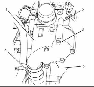
g01282186
Illustration 37
g01282186
Illustration 36
1. Install a new O-ring seal (10) to oil cooler bonnet
(5). Apply Tooling (A) to the O-ring seal. Install
joint (6) to oil cooler bonnet (5). Position the oil
cooler bonnet on the water pump and install bolts
(11). Tighten the bolts finger tight.
2. Remove bolts (1). Remove outlet bonnet (3) from
the cylinder block and from the engine oil cooler.
Remove joint (2) and O-ring seal (7) from the
outlet bonnet.
2. Install two new O-ring seals (9) to the engine oil
3. Remove bolts (8). Rotate core assembly (4) and
slide the core assembly toward the rear of the
engine in order to remove the core assembly from
the engine oil filter base. Remove O-ring seals (9)
from the engine oil filter base.
filter base.
3. Slide core assembly (4) toward the front of the
engine. Rotate the core assembly into position.
Install bolts (8). Tighten the bolts finger tight.
4. Remove bolts (11). Remove oil cooler bonnet (5)
from the water pump. Remove joint (6) and O-ring
seal (10) from the oil cooler bonnet.
4. Install a new O-ring seal (7) to outlet bonnet (3).
Apply Tooling (A) to the O-ring seal. Install joint (2)
to outlet bonnet (3). Position outlet bonnet (3) on
the core assembly and install bolts (1). Tighten
the bolts finger tight.
5. Tighten bolts (8), (1) and (11) to a torque of
47 N·m (35 lb ft).
This document has been printed from SPI². Not for Resale
![]()
![]()
![]()
![]()
![]()
![]()
![]()
24
KENR6232
Disassembly and Assembly Section
6. Fill the cooling system. Refer to Operation and
Maintenance Manual, “Cooling System Coolant
- Change”.
2. Remove the fasteners and remove the assembly
of the suction pipe (2). Remove the O-ring seal
from the tube assembly.
7. Check the level of the engine lubricating oil. Refer
to Operation and Maintenance Manual, “Engine
Oil Level - Check”.
3. Remove bolts (5) and remove engine oil pump (1)
from the cylinder block.
4. If necessary, remove bolts (4) and remove
underframe assembly (3).
i02554736
Engine Oil Pump - Remove
i02554733
Engine Oil Pump - Disassemble
Removal Procedure
Start By:
Disassembly Procedure
a. Remove the engine oil pan. Refer to Disassembly
and Assembly, “Engine Oil Pan - Remove and
Install”.
Table 14
Required Tools
Tool
Part Number
Part Description
Qty
NOTICE
A
-
Puller (Three Leg)
1
Care must be taken to ensure that fluids are contained
during performance of inspection, maintenance, test-
ing, adjusting and repair of the product. Be prepared to
collect the fluid with suitable containers before open-
ing any compartment or disassembling any compo-
nent containing fluids.
Start By:
a. Remove the engine oil pump. Refer to
Disassembly and Assembly, “Engine Oil Pump -
Remove”.
Dispose of all fluids according to local regulations and
mandates.
NOTICE
Keep all parts clean from contaminants.
NOTICE
Contaminants may cause rapid wear and shortened
component life.
Keep all parts clean from contaminants.
Contaminants may cause rapid wear and shortened
component life.
g01077736
Illustration 38
Typical example
1. Remove the fasteners and remove tube assembly
(6). Remove the O-ring seal from the tube
assembly.
g01001918
Illustration 39
This document has been printed from SPI². Not for Resale
![]()
![]()
![]()
![]()
![]()
![]()

![]()
![]()
![]()
KENR6232
25
Disassembly and Assembly Section
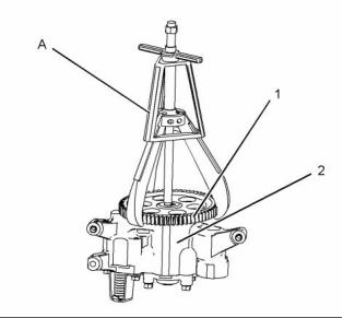
1. Remove the bolt that holds drive gear (1) to the
shaft of engine oil pump (2). Use Tooling (A) to
remove the drive gear from the shaft. Remove the
key from the shaft.
g01103246
Illustration 41
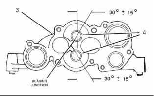
1. Use a press and a suitable tool to install sleeve
bearings (4) in pump body (3). The bearing joint
should be 30 ± 15 degrees from the center line of
the two bearing bores. Install the sleeve bearings
so the sleeve bearings are even with the outside
of the pump body.
g01101672
Illustration 40
Personal injury can result from parts and/or cov-
ers under spring pressure.
Spring force will be released when covers are re-
moved.
Be prepared to hold spring loaded covers as the
bolts are loosened.
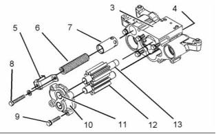
2. Remove bolts (8). Remove retainer (5), spring (6),
and relief plunger (7) from pump body (3).
3. Remove bolts (9) and cover (10).
g01101732
4. Remove idler gear (12) and drive gear (13) from
Illustration 42
the pump body.
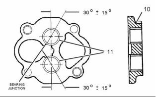
2. Use a press and a suitable tool to install sleeve
bearings (11) in cover (10). The bearing joint
should be 30 ± 15 degrees from the center line of
the two bearing bores. Install the sleeve bearings
so the sleeve bearings are even with the outside
of the cover.
5. Use a suitable tool to remove sleeve bearings (4)
from the pump body.
6. Use a suitable tool to remove sleeve bearings (11)
from the cover.
i02554732
Engine Oil Pump - Assemble
Assembly Procedure
NOTICE
Keep all parts clean from contaminants.
Contaminants may cause rapid wear and shortened
component life.
g01101672
Illustration 43
This document has been printed from SPI². Not for Resale
![]()
![]()
![]()
![]()
![]()
![]()
![]()
![]()
![]()
26
KENR6232
Disassembly and Assembly Section
i02554734
Engine Oil Pump - Install
Improper assembly of parts that are spring loaded
can cause bodily injury.
To prevent possible injury, follow the established
assembly procedure and wear protective equip-
ment.
Installation Procedure
NOTICE
Keep all parts clean from contaminants.
3. Lubricate the idler gear and the drive gear with
clean engine oil. Lubricate sleeve bearings (4)
with clean engine oil. Install idler gear (12) and
drive gear (13) in pump body (3).
Contaminants may cause rapid wear and shortened
component life.
4. Lubricate sleeve bearings (11) with clean engine
oil. Install cover (10). Install bolts (9).
Note: The engine oil pump must turn freely after
assembly. Turn the engine oil pump by hand.
Reposition cover (10) if the engine oil pump does not
turn freely.
5. Install relief plunger (7), spring (6), retainer (5),
and bolts (8).
6. Install the key on the shaft.
g01077736
Illustration 45
Typical example
1. Position underframe assembly (3) on the cylinder
block. Install bolts (4). Tighten the bolts to a torque
of 47 N·m (35 lb ft).
2. Position engine oil pump (1) on the dowels in the
cylinder block. Install bolts (5). Tighten the bolts
to a torque of 47 N·m (35 lb ft).
Note: Ensure that the engine oil pump is seated on
the dowels before the bolts are tightened.
g01101743
Illustration 44
3. Install a new O-ring seal to tube assembly (6).
Lubricate the bore in the engine oil pump with
clean engine oil. Install tube assembly (6). Install
the bolts that secure the tube assembly. Tighten
the bolts to a torque of 47 N·m (35 lb ft).
7. Install drive gear (1) on the shaft of engine oil
pump (2). Install bolt (14). Tighten the bolt to a
torque of 55 N·m (41 lb ft).
End By:
4. Install a new O-ring seal to the assembly of
suction pipe (2). Lubricate the bore in the engine
oil pump with clean engine oil. Install the assembly
of suction pipe (2). Install the bolts and washers
that secure the tube assembly. Tighten the bolts
to a torque of 47 N·m (35 lb ft).
a. Install the engine oil pump. Refer to Disassembly
and Assembly, “Engine Oil Pump - Install”.
End By:
a. Install the engine oil pan. Refer to Disassembly
and Assembly, “Engine Oil Pan - Remove and
Install”.
This document has been printed from SPI². Not for Resale
![]()
![]()
![]()
![]()
![]()
![]()
![]()
KENR6232
27
Disassembly and Assembly Section
i02554791
Water Pump - Remove
Removal Procedure
NOTICE
Care must be taken to ensure that fluids are contained
during performance of inspection, maintenance, test-
ing, adjusting and repair of the product. Be prepared to
collect the fluid with suitable containers before open-
ing any compartment or disassembling any compo-
nent containing fluids.
Dispose of all fluids according to local regulations and
mandates.
NOTICE
Keep all parts clean from contaminants.
Contaminants may cause rapid wear and shortened
component life.
1. Drain the coolant from the cooling system into
a suitable container for storage or for disposal.
Refer to Operation and Maintenance Manual,
“Cooling System Coolant - Change”.
g01285782
Illustration 46
2. Remove bolts (2) from water temperature regulator
housing (1). Remove water temperature regulator
housing (1) and pipe (3) as a unit. Remove the
O-ring seals from the water temperature regulator
housing and the pipe.
3. Remove bolts (5). Remove water pump cover (4)
from water pump (8). Remove the O-ring seal from
the water pump cover.
4. Remove bolts (7). Remove oil cooler bonnet (6)
from the engine oil cooler. Remove the joint and
the O-ring seal from the oil cooler bonnet.
5. Remove the belt tightener. Refer to Disassembly
and Assembly, “Belt Tightener - Remove”.
6. Attach a suitable lifting device to water pump (8).
Support the weight of the water pump. The water
pump weighs approximately 18.3 kg (40 lb).
7. Remove bolts (9).
8. Use the lifting device in order to remove water
pump (8) from the front housing. Remove the
O-ring seal from the water pump.
This document has been printed from SPI². Not for Resale
![]()
![]()
![]()
![]()
![]()
![]()
28
KENR6232
Disassembly and Assembly Section
i02554790
2. Use a suitable lifting device in order to position
water pump (8) on the front housing. The water
pump weighs approximately 18.3 kg (40 lb).
Water Pump - Install
3. Install bolts (9). Tighten the bolts to a torque of
47 N·m (35 lb ft).
Installation Procedure
4. Install the belt tightener. Refer to Disassembly and
Table 15
Assembly, “Belt Tightener - Install”.
Required Tools
5. Install a new O-ring seal on oil cooler bonnet (6).
Apply Tooling (A) to the O-ring seal. Position the
joint and install oil cooler bonnet (6) to the engine
oil cooler. Install bolts (7). Tighten the bolts to a
torque of 47 N·m (35 lb ft).
Tool
Part Number
Part Description
Qty
POWERPART
A
21820221
1
Rubber Grease
NOTICE
6. Install a new O-ring seal to water pump cover (4).
Position water pump cover (4) on water pump (8)
and install bolts (5). Tighten the bolts to a torque
of 47 N·m (35 lb ft).
Keep all parts clean from contaminants.
Contaminants may cause rapid wear and shortened
component life.
7. Install new O-ring seals to pipe (3). Apply Tooling
(A) to the O-ring seals. Install the pipe in the
water temperature regulator housing (1). Install a
new O-ring seal to water temperature regulator
housing (1).
8. Insert pipe (3) into water pump cover (4). Install
the assembly of the water temperature regulator
housing and pipe as a unit. Install bolts (2).
Tighten the bolts to a torque of 47 N·m (35 lb ft).
9. Fill the cooling system. Refer to Operation and
Maintenance Manual, “Cooling System Coolant
- Change”.
i02554792
Water Temperature Regulator
Housing - Remove and Install
Removal Procedure
NOTICE
Care must be taken to ensure that fluids are contained
during performance of inspection, maintenance, test-
ing, adjusting and repair of the product. Be prepared to
collect the fluid with suitable containers before open-
ing any compartment or disassembling any compo-
nent containing fluids.
Dispose of all fluids according to local regulations and
mandates.
g01285782
Illustration 47
1. Install a new O-ring seal to water pump (8).
This document has been printed from SPI². Not for Resale
![]()

![]()
![]()
![]()
![]()
![]()
KENR6232
29
Disassembly and Assembly Section
NOTICE
Keep all parts clean from contaminants.
Contaminants may cause rapid wear and shortened
component life.
1. Drain the coolant from the cooling system into
a suitable container for storage or for disposal.
Refer to Operation and Maintenance Manual,
“Cooling System Coolant - Change”.
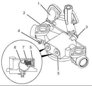
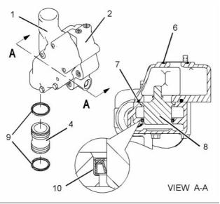
g01282552
Illustration 49
4. Remove water temperature regulator housing (1)
from housing manifold (2). Remove O-ring seal (7)
and O-ring seal (6) from the housing manifold.
5. Remove water temperature regulators (8).
6. Remove lip seal (10).
7. Remove pipe (4) from the water temperature
regulator housing. Remove O-ring seals (9) from
pipe (4).
g01282550
Illustration 48
Typical example
8. If necessary, remove coolant temperature sensor
(5). Refer to Disassembly and Assembly, “Coolant
Temperature Sensor - Remove and Install”.
2. Slide the locking tab into the unlocked position and
disconnect the harness assembly from coolant
temperature sensor (5).
Installation Procedure
3. Remove bolts (3). Remove pipe (4), water
temperature regulator housing (1), and housing
manifold (2).
Table 16
Required Tools
Tool
Part Number
Part Description
Seal Installer
Qty
A
27610309
1
POWERPART
Rubber Grease
B
218200221
1
NOTICE
Keep all parts clean from contaminants.
Contaminants may cause rapid wear and shortened
component life.
This document has been printed from SPI². Not for Resale
![]()
![]()
![]()
![]()
![]()

![]()
![]()
30
KENR6232
Disassembly and Assembly Section
5. Loosely install bolts (3) to water temperature
regulator housing (1) and housing manifold (2).
Position water temperature regulator housing (1)
and housing manifold (2) onto pipe (4). Tighten
the bolts to a torque of 47 N·m (35 lb ft).
6. If necessary, install coolant temperature sensor
(5). Refer to Disassembly and Assembly, “Coolant
Temperature Sensor - Remove and Install”.
7. Connect the harness assembly to coolant
temperature sensor (5). Slide the locking tab into
the locked position.
8. Fill the cooling system. Refer to Operation and
Maintenance Manual, “Cooling System Coolant
- Change”.
i02554737
Engine Support (Front) -
Remove and Install
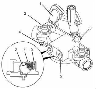
g01282552
Illustration 50
1. Use Tooling (A) to install lip seals (10) into water
temperature regulator housing (1).
Removal Procedure
2. Install new O-ring seals (9) onto pipe (4). Apply
Tooling (B) to the O-ring seals. Install pipe (4) to
the water pump.
Table 17
Required Tools
3. Install O-ring seal (6) and O-ring seal (7) to
housing manifold (2).
Tool
Part Number
Part Description
Guide Stud
Qty
A
-
2
4. Install water temperature regulators (8) into the
(1/2 - 13 UNC by 6 inch)
water temperature regulator housing (1).
Start By:
a. Remove the assembly of the vibration damper
and the crankshaft pulley. Refer to Disassembly
and Assembly, “Vibration Damper and Pulley -
Remove and Install”.
1. Support the front of the engine.
g01282550
Illustration 51
Typical example
g01286145
Illustration 52
This document has been printed from SPI². Not for Resale
![]()
![]()
![]()

![]()
KENR6232
31
Disassembly and Assembly Section
2. Remove bolts (1) and install Tooling (A). Remove
End By:
the remaining bolts.
a. Install the assembly of the vibration damper
and the crankshaft pulley. Refer to Disassembly
and Assembly, “Vibration Damper and Pulley -
Remove and Install”.
3. Remove engine support (2) from the cylinder
block. The weight of engine support (2) is
approximately 33.5 kg (74 lb).
Installation Procedure
i02554746
Flywheel - Remove
Table 18
Required Tools
Tool
Part Number
Part Description
Guide Stud
Qty
Removal Procedure
A
-
2
(1/2 - 13 UNC by 6 inch)
Table 19
1. Support the front of the engine.
Required Tools
Part
Tool
Number
Part Description
Qty
Guide Stud
5/8 - 18 by 8 inch
A
-
2
Start By:
a. Remove the electric starting motor. Refer to
Disassembly and Assembly, “Electric Starting
Motor - Remove and Install”.
NOTICE
Keep all parts clean from contaminants.
g01286145
Illustration 53
Contaminants may cause rapid wear and shortened
component life.
2. Position engine support (2) on Tooling (A). The
weight of engine support (2) is approximately
33.5 kg (74 lb).
3. Install bolts (1) finger tight. Remove Tooling (A)
and install the remaining bolts.
g01282130
Illustration 55
Typical example
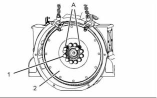
1. Use a suitable tool to lock the flywheel. Loosen
bolts (1).
g01286401
Illustration 54
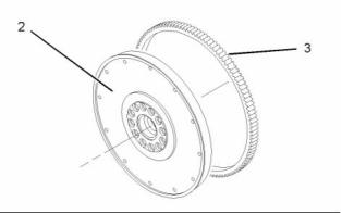
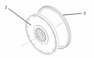
2. Attach a suitable lifting device to flywheel (1).
Support the weight of the flywheel. The weight of
flywheel (2) is approximately 130 kg (286 lb).
Tightening sequence
4. Install bolts (1). Tighten the bolts to a torque of
105 N·m (77 lb ft) in the order that is shown in
Illustration 54.
3. Remove two bolts (1). Install Tooling (A).
This document has been printed from SPI². Not for Resale
![]()

![]()
![]()
![]()
![]()
![]()

32
KENR6232
Disassembly and Assembly Section
4. Remove the remaining bolts (1). Use the lifting
device in order to remove flywheel (2).
g01091705
Illustration 57
g01091705
Illustration 56
Typical example
Always wear protective gloves when handling
parts that have been heated.
5. Inspect flywheel (2) and ring gear (3) for wear or
damage. Replace any components that are worn
or damaged.
1. If the flywheel ring gear was removed, follow
Steps 1.a through 1.c in order to install a new ring
gear to the flywheel.
6. To remove the flywheel ring gear, follow Steps 6.a
and 6.b.
a. Identify the orientation of the teeth on the new
a. Place the flywheel assembly on a suitable
ring gear (3).
support.
Note: The chamfered side of the ring gear teeth must
face toward the starting motor when the flywheel is
installed. This will ensure the correct engagement of
the starting motor.
Note: Identify the orientation of the teeth on the
flywheel ring gear.
b. Use a hammer and a punch in order to remove
ring gear (3) from flywheel (2).
b. Heat flywheel ring gear (3) in an oven to a
maximum temperature of 316 °C (600 °F) prior
to installation.
i02554744
Flywheel - Install
Note: Do not use a torch to heat the ring gear.
c. Ensure that the orientation of ring gear (3) is
correct and quickly install the ring gear onto
flywheel (2).
Installation Procedure
2. Inspect the crankshaft rear seal for leaks. If there
are any oil leaks, replace the crankshaft rear seal.
Refer to Disassembly and Assembly, “Crankshaft
Rear Seal - Remove”.
Table 20
Required Tools
Tool
Part Number
Part Description
Qty
Guide Stud
A
-
2
5/8 - 18 by 8 inch
NOTICE
Keep all parts clean from contaminants.
Contaminants may cause rapid wear and shortened
component life.
This document has been printed from SPI². Not for Resale
![]()
![]()
![]()
![]()
![]()
![]()
![]()
![]()
KENR6232
33
Disassembly and Assembly Section
Start By:<, /P>
a. Remove the flywheel. Refer to Disassembly and
Assembly, “Flywheel - Remove”.
NOTICE
Keep all parts clean from contaminants.
Contaminants may cause rapid wear and shortened
component life.
Note: The crankshaft rear seal and the wear sleeve
must be replaced as a unit. Once the crankshaft
rear seal and the wear sleeve are separated, these
components can not be used again.
g01282130
Illustration 58
Typical example
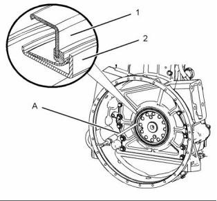
3. Install a suitable lifting device to flywheel (1). The
weight of flywheel (2) is approximately 130 kg
(287 lb).
4. Install Tooling (A) on the crankshaft.
5. Use the lifting device in order to position flywheel
(1) onto Tooling (A).
6. Apply clean engine oil to the threads of bolts (1).
7. Install bolts (1). Remove Tooling (A). Install
remaining bolts (1).
8. Use a suitable tool to prevent the flywheel from
rotating. Tighten bolts (1) to a torque of 270 N·m
(200 lb ft).
9. Remove the lifting device from flywheel (1).
g01007851
Illustration 59
Typical example
10. Check the runout of the flywheel. Refer to
Systems Operations, Testing and Adjusting,
“Flywheel - Inspect”.
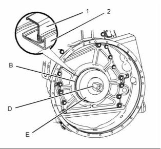
1. Use a 4 mm (0.158 inch) drill in order to make
three or more holes in wear sleeve (2).
End By:
2. Use Tooling (A) to remove the wear sleeve.
a. Install the electric starting motor. Refer to
Disassembly and Assembly, “Electric Starting
Motor - Remove and Install”.
3. Use a 4 mm (0.158 inch) drill in order to make
three or more holes in crankshaft rear seal (1).
i02554710
4. Use Tooling (A) to remove crankshaft rear seal (1).
Crankshaft Rear Seal - Remove
Removal Procedure
Table 21
Required Tools
Part
Tool
Number
Part Description
Qty
A
27610311
Slide Hammer Puller
1
This document has been printed from SPI². Not for Resale
![]()
![]()

![]()
![]()
![]()
34
KENR6232
Disassembly and Assembly Section
i02554709
Crankshaft Rear Seal - Install
1. Before installation of the crankshaft seal and the
wear sleeve, inspect the crankshaft for scratches.
Also, inspect the crankshaft for any distortion
on the surface that may lead to an out of round
condition. Use a polishing cloth in order to remove
any imperfections on the crankshaft.
Installation Procedure
2. Clean the outside diameter of the crankshaft and
Table 22
the inside diameter of the wear sleeve.
Required Tools
Part
3. Fasten Tooling (B) to the crankshaft with Tooling
(C).
Tool
B
Number
GE50008
GE50009
GE50014
GE50013
Part Description
Qty
1
Note: Install the crankshaft rear seal with the arrow
that shows the direction of crankshaft rotation toward
the rear of the engine.
Seal Locator
C
Bolt
3
D
Nut (Seal Installer)
Seal Installer
1
4. Position wear sleeve (2) and crankshaft rear seal
(1) on Tooling (B). Install Tooling (E) on Tooling
(B). Lubricate the face of the washer on Tooling
(D). Install Tooling (D) on Tooling (B).
E
1
NOTICE
Keep all parts clean from contaminants.
5. Tighten Tooling (D) until Tooling (E) contacts
Tooling (B).
Contaminants may cause rapid wear and shortened
component life.
6. Remove Tooling (D) and Tooling (E) from Tooling
(B).
Note: Do not lubricate the crankshaft seal or the wear
7. Remove Tooling (C) and Tooling (B) from the
sleeve. The crankshaft seal must be installed dry.
crankshaft.
8. Check the crankshaft rear seal and the wear
sleeve for the correct installation.
End By:
a. Install the flywheel. Refer to Disassembly and
Assembly, “Flywheel - Install”.
i02554749
Flywheel Housing - Remove
and Install
Removal Procedure
Table 23
g01007913
Required Tools
Illustration 60
Typical example
Tool
Part Number
Part Description
Guide Stud
Qty
Note: Do not use any type of lubricant during the
A
-
2
(3/8 - 16 x 4inch)
installation of the crankshaft seal and wear sleeve.
This document has been printed from SPI². Not for Resale
![]()

![]()
![]()
![]()

KENR6232
35
Disassembly and Assembly Section
Start By:
3. Remove remaining bolts (2). Use the suitable
lifting device to remove the flywheel housing from
the cylinder block.
a. Remove the electric starting motor. Refer to
Disassembly and Assembly, “Electric Starting
Motor - Remove”.
Note: It is not necessary to remove the dowels in the
cylinder block that locate the flywheel housing.
b. Remove the crankshaft rear seal. Refer to
Disassembly and Assembly, “Crankshaft Rear
Seal - Remove”.
Installation Procedure
Table 24
c. Remove the engine oil pan. Refer to Disassembly
and Assembly, “Engine Oil Pan - Remove and
Install”.
Required Tools
Tool
A
Part Number
Part Description
Qty
2
Guide Stud
NOTICE
-
(3/8 - 16 x 4inch)
Sealant
Care must be taken to ensure that fluids are contained
during performance of inspection, maintenance, test-
ing, adjusting and repair of the product. Be prepared to
collect the fluid with suitable containers before open-
ing any compartment or disassembling any compo-
nent containing fluids.
B
CH10879
1
NOTICE
Keep all parts clean from contaminants.
Contaminants may cause rapid wear and shortened
component life.
Dispose of all fluids according to local regulations and
mandates.
1. Thoroughly clean the flywheel housing and the
rear surface of the cylinder block. Ensure that the
dowels in the cylinder block protrude 1.91 cm
(0.75 inch) from the mating surface.
NOTICE
Keep all parts clean from contaminants.
Contaminants may cause rapid wear and shortened
component life.
g01287855
Illustration 62
Typical example
g01287855
Illustration 61
Typical example
2. Install Tooling (A) in the cylinder block.
1. Install a suitable lifting device to flywheel housing
(1). The weight of the flywheel housing is
approximately 86 kg (190 lb).
a suitable lifting device to flywheel housing
3. Install
(1). The weight of the flywheel housing is
approximately 86 kg (190 lb).
2. Remove two bolts (2). Install Tooling (A).
4. Apply Tooling (B) to the rear face of the cylinder
block.
This document has been printed from SPI². Not for Resale
![]()
![]()
![]()
![]()
![]()
![]()
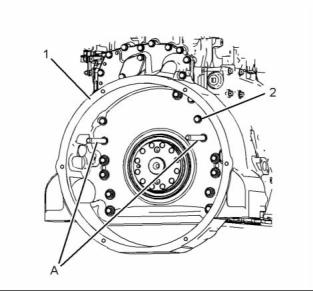
![]()
![]()
![]()
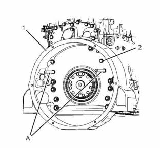
36
KENR6232
Disassembly and Assembly Section
Note: The flywheel housing must be installed within
i02554787
Vibration Damper and Pulley -
Remove and Install
ten minutes of applying Tooling (B).
5. Use the suitable lifting device to align flywheel
housing (1) with Tooling (A). Install the flywheel
housing to the cylinder block. Install bolts (2)
finger tight. Remove Tooling (A) and install the
remaining bolts.
Removal Procedure
Table 25
Required Tools
Tool
Part Number
Part Description
Guide Stud
Qty
A
-
2
(5/8 - 18 x 9 inch)
Start By:
a. Remove the fan. Refer to Disassembly and
Assembly, “Fan - Remove and Install”.
NOTICE
Keep all parts clean from contaminants.
Contaminants may cause rapid wear and shortened
component life.
g00551652
Illustration 63
Tightening sequence
Typical example
6. Tighten the bolts, as follows:
a. In the numerical sequence, tighten bolt 1
through bolt 9 to a torque of 100 N·m (74 lb ft).
b. In the numerical sequence, tighten bolt 10
through bolt 24 to a torque of 40 N·m (30 lb ft).
c. In the numerical sequence, tighten bolt 1
through bolt 9 to a torque of 135 N·m (100 lb ft).
d. In the numerical sequence, tighten bolt 10
through bolt 24 to a torque of 55 N·m (41 lb ft).
End By:
g01285717
a. Install the crankshaft rear seal. Refer to
Disassembly and Assembly, “Crankshaft Rear
Seal - Install”.
Illustration 64
1. Loosen nut (1). Rotate bolt (2) in order to release
the tension on the V-belts.
b. Install the engine oil pan. Refer to Disassembly
and Assembly, “Engine Oil Pan - Remove and
Install”.
c. Install the electric starting motor. Refer to
Disassembly and Assembly, “Electric Starting
Motor - Remove and Install”.
This document has been printed from SPI². Not for Resale
![]()
![]()
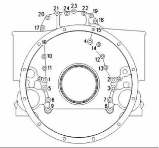

![]()
![]()
![]()
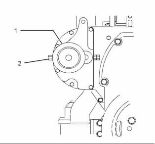
KENR6232
37
Disassembly and Assembly Section
Installation Procedure
Table 26
Required Tools
Part Number Part Description
Tool
A
Qty
Guide Stud
-
2
-
(5/8 - 18 x 9 inch)
B
CV60890
Anti-Seize Compound
NOTICE
Keep all parts clean from contaminants.
Contaminants may cause rapid wear and shortened
component life.
g01286051
Illustration 65
Typical example
2. Remove the V-belts from crankshaft pulley (6).
Temporarily secure the V-belts in a position that
is clear of vibration damper (4).
NOTICE
Thoroughly inspect the viscous damper for signs of
leakage or for signs of a dented (damaged) case.
Either of these conditions can cause the weight to
make contact with the case. This can affect the vis-
cous damper’s operation.
3. Remove two bolts (5). Install Tooling (A).
4. Remove remaining bolts (5). Remove crankshaft
pulley (6).
Note: Ensure that the weight of the assembly of
vibration damper (4) and adapter (3) is adequately
supported.
5. Install a suitable lifting device to the assembly of
vibration damper (4) and adapter (3). The weight
of the assembly of the vibration damper and the
adapter is approximately 50 kg (110 lb).
6. Use the lifting device to remove the assembly of
vibration damper (4) and adapter (3) from the
crankshaft.
g01286057
Illustration 67
7. Remove Tooling (A) from the crankshaft.
1. Inspect the components for damage. Replace any
免費(fèi)熱線
400-100-8969???15088860848
400-100-8969???15088860848
機(jī)組銷售
0574-26871589? 15267810868
0574-26871589? 15267810868
配件銷售
0574-26886646? 15706865167
0574-26886646? 15706865167
維修熱線
0574-26871569 18658287286
0574-26871569 18658287286
手機(jī)端

微信公眾號
在線客服