English
 Espaol
 Franais
 阿拉伯
阿拉伯 中文(簡)
中文(簡) Deutsch
 Italiano
 Português
 日本
日本 韓國
韓國 български
 hrvatski
 esky
esky Dansk
Dansk Nederlands
 suomi
suomi Ελληνικ
 印度
印度 norsk
norsk Polski
 Roman
Roman русский
 Svenska
帕金斯2806柴油發電機ECM接線原理圖說明
帕金斯2806柴油發電機ECM接線原理圖說明
ECM terminal connections
Note: Using ECM connector P1.
2800 Series
13 12
11
10
9
8
7
6
5
4
3
2
1
Function
Pin Location
23
22
21 20
19
18
17
16
15
14
Shutdown Lamp
10
31
39
47
57
30
38
46
56
29 28
37 36
45 44
55 54
53
52
27 26
35 34
43 42
51 50
25
33
41
49
24
32
40
48
Action Alert Lamp
Warning Lamp
Diagnostics Lamp
Oil Pressure Lamp
19
20
31
28
70
69
68
67 66
65
64
63
62
61
60
59
58
Coolant Temp Lamp
Overspeed Lamp
Crank Terminate Output
29
30
Terminal side
13
57
47
31
70
69
68
67
66
36
65
64
63
62
61
60
59
58
48
40
24
23
13
12
11
10
9
>PEI<
8 7
6
5
4
3
2
1
14
B
Wire side
HA0020
106
![]()
![]()
![]()
![]() 2800 Series
2800 Series
4
+5 V Sensor voltage supply circuit test
Test 43
Diagnostic codes
System operation
Functional test
Use this procedure to diagnose the system when there is an active, or easily repeated, 262-03 +5 V Supply
Above Normal or 262-04 +5 V Supply Below Normal or if directed here by another diagnostic procedure.
The Electronic Control Module (ECM) supplies +5 V to the oil pressure, atmospheric pressure and turbo outlet
pressure sensors. The +5 V sensor supply is routed from the ECM through the ECM engine harness connector
J2/P2 terminal-2 to terminal-A of each +5 V sensor connector. The supply voltage is 5.0 +/- 0.5 Volts DC.
The +5 V short circuit diagnostic code is most likely caus ed by a short or open circuit in the harness, next likely
is a sensor, and least likely is the ECM.
5 V supply to analogue sensor schematic
Note: Refer to the wiring diagrams for full connection details.
|
|
|
|
Return B
Turbo Outlet Pressure Sensor
Return B
J2/2
J2/14
J2/3
J2/40
+5VDC Suppl y
Atmospheric Pressure
Analogue Return
ECM
Intake Manifold Pressure
|
|
Return
A
C
B
J2/24
Oil Pressure
A
HA0021
107
![]() 4
4
Diagnostic codes
2800 Series
|
Diagnostic fault code |
Conditions that could cause the code |
System response |
To find the fault |
|
262-03 |
+5 V Supply Above Normal The ECM supply voltage for the sensors is exceeding normal level, indicating a possible short to a positive voltage source. |
Electronic system response All ECM +5 V analogue sensor inputs assume default values and all diagnostic codes for ECM +5 V analogue sensors are disabled while this diagnostic code is active. TIPSS may indicate DIAG next to the default value Sensor Status to indicate the sensor is operating at the value shown due to an active diagnostic code. This diagnostic code remains active until the engine control switch is turned to the OFF position. Note: Since engine protection is no longer available, the engine is shut down. |
Proceed with Test 43: +5 V Sensor voltage supply circuit test. |
|
262-04 |
+5 V Supply Below Normal The ECM supply voltage for the intake manifold pressure, atmospheric pressure and oil pressure sensors is below normal level, indicating a possible short to ground or short between sensor supply and return. |
Electronic system response All ECM +5 V analogue sensor inputs assume default values and all diagnostic codes for ECM +5 V analogue sensors are disabled while this diagnostic code is active. TIPSS may indicate DIAG next to the default value Sensor Status to indicate the sensor is operating at the value shown due to an active diagnostic code. This diagnostic code remains active until the key switch is turned to the OFF position. Note: Since engine protection is no longer available, the engine is shut down. |
Proceed with Test 42: ECM Status indicator output circuit test. |
108

![]() 2800 Series
2800 Series
Functional test
4
Test 43 - +5 V Sensor voltage supply circuit test
Test step Result
Step 1: Connect an electronic service tool and note all active diagnostic codes
Connect the TIPSS-EST service tool to the service tool ACTIVE
connector.
Turn the key switch to the ON position.
Access the TIPSS "Active" and "Logged Diagnostic Code" LOGGED ONLY
screen(s) (wait at least 15 seconds for diagnostic codes to
become active).
Check for active or logged 262-03 +5 V Supply Above Normal
or 262-04 +5 V Supply Below Normal diagnostic codes.
Select the condition of code 262-03 or 262-04.
NOT ACTIVE OR
LOGGED
Step 2: Disconnect +5 V sensors and monitor active diagnostic codes
Access the "Active Diagnostic Code" screen and check there is
an active +5 V Sensor Supply diagnostic code (262-03 or
262-04).
Disconnect the following sensors and turn the key switch to the
OFF position, then to the ON position: oil pressure,
atmospheric pressure and turbo outlet pressure sensors.
Check the TIPSS-EST screen after disconnecting each sensor
to determine if disconnection of a specific sensor deactivates
the +5 V diagnostic code.
Note: When the sensors are disconnected and the key switch is in
the ON position, open circuit diagnostic codes will be active/logged
when the +5 V diagnostic codes are no longer acti ve. This is
normal. Clear these diagnostic codes after this test step is
completed.
Is the original +5 V diagnostic code (262-03 or 262-04) still
active ?
Action
A 262-03 or 262-04
diagnostic code is active.
Go to step 2.
A 262-03 or 262-04
diagnostic code is logged
but NOT active.
Refer to Test 39: Inspecting
electrical connectors on
page 82.
If OK, Go to step 4..
The +5 V sensor supply is
operating correctly at this
time.
STOP.
The +5 V diagnostic code is
still active.
Leave the sensors
disconnected.
Go to step 3.
Disconnecting a specific
sensor makes the +5 V
diagnostic code no longer
active.
Reconnect the sensor
suspected of causing the
problem.
If the problem reappears,
and then disappears
following disconnection,
renew the sensor.
Clear all diagnostic codes.
Check that the repair
eliminates the fault.
STOP.
109

![]() 4
4
2800 Series
Test 43 - +5 V Sensor voltage supply circuit test (Continued)
Test step Result
Step 3: Isolate the sensor supply harness From The ECM
Action
Remove power from the engine control system. Turn the key
switch to the OFF position and disconnect the power from the
engine.
Disconnect J2/P2 and inspect for damage or corrosion. Repair
as necessary.
Use a wire removal tool to remove the +5 V supply wire from
ECM connector P2 terminal-2. Reconnect J2/P2.
Restore power to the engine control system and turn the key
switch to the ON position.
Access the "Active Diagnostic Code" screen and determine
there is an active +5 V Sensor Supply diagnostic code (262-03
or 262-04).
Does the +5 V diagnostic code remain active with the engine
harness isolated ?
Step 4: Check the engine harness
Remove power from the engine control system. Turn the key
switch to the OFF position and disconnect the power from the
engine.
Disconnect P2 and check ALL of the +5 V engine sensors
attached to the P2 engine harness are di sconnected (oil
pressure, atmospheric pressure and turbo outlet pressure
sensors).
Set a multimeter to measure resistance on the range closest to,
but not less than, 2k Ohms. Measure from P1 terminal-2 (+5 V
Supply) to each of the sensor signal terminals (P1
terminals-14, 17, 24, 26, and 27) and to P1 terminal-3
(analogue return). Wiggle the harness during measurement to
reveal any intermittent short condition. Refer to "ECM terminal
connections" on page 111.
Measure the resistance from P2 terminal-2 (+5 V Supply) to
engine ground.
Each resistance measurement is more than 2k Ohms.
Isolating the engine harness
from the ECM does not
eliminate the active +5 V
Sensor Supply diagnostic
code.
Renew the ECM.
STOP.
The +5 V Sensor Supply
diagnostic code is no longer
active when the harness is
isolated.
There is a short circuit in the
harness.
Refer to Test 39: Inspecting
electrical connectors on
page 82.
If OK, Go to step 4..
The +5 V line is not shorted
in the engine harness.
Reconnect all connectors.
There does not appear to be
a problem at this time.
Clear all diagnostic codes.
Continue to diagnose until
the original condition is
resolved.
STOP.
Repair the engine harness.
Clear all logged diagnostic
codes.
Check that the repair
eliminates the fault.
STOP.
110
![]() 2800 Series
2800 Series
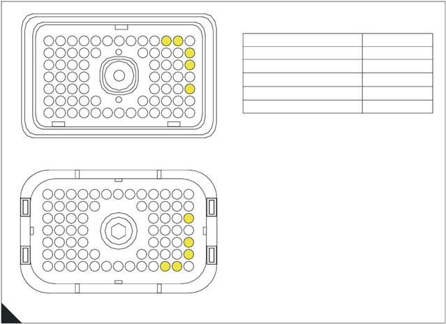
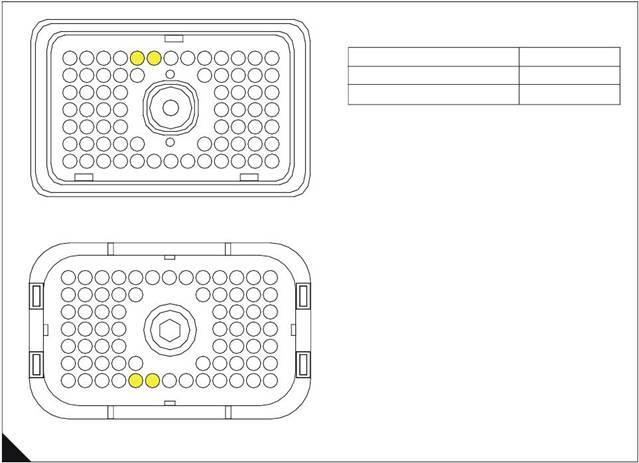
ECM terminal connections
Note: Using ECM connector P2.
4
13
23
31
12
22
30
11
21
29
10
20
28
9
19
8
7
6
5
18
4
17
27
3
16
26
2
15
25
1
14
24
Function
+5 VDC Supply
Analog Return
Pin Location
2
3
39
47
57
38
46
56
37 36
45 44
55 54 53
52
35
43
51
34
42
50
33 32
41 40
49 48
Intake Manifold Pressure
Atmospheric Pressure
Oil Pressure
40
14
24
70
69
68
67 66
65
64 63
62 61
60
59 58
Terminal side
57
47
31
23
70
69
68
67 66
36
65
64
63
62 61
60
59 58
48
40
24
14
13
12
11
10
9
>PEI<
8 7
6
5
4
3
2
1
B
Wire side
HA0022
111
![]()
![]()
![]()

![]() 4
4
2800 Series
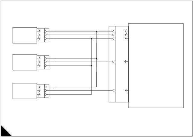
PWM desired speed setting circuit test
Test 44
Diagnostic codes
System operation
Functional test
Note: This procedure is only applicable if the PWM speed control method is selected.
Use this procedure if a 91-08 Invalid PWM Speed Control Signal, 41-03 8 Volt Supply Above Normal or 41-04
8 Volt Supply Below Normal diagnostic code is indicated.
PWM speed control
The PWM speed control is used to provide a desired speed setting signal to the ECM. Output is a constant
frequenc y signal with a pulse width that varies with the speed control signal. This output signal is referred to
as either “Duty Cycle” or a “Pulse Width Modulated” (PWM) signal and is expressed as a percentage between
3 and 100 percent.
Note: The PWM speed control is an external device supplied by the OEM.
The speed control must produce a duty cycle of 2.6 to 9.9 percent for 1141 rev/min (1369 rev/min if 1800 rev/
min is selected) and 90.1 to 95 percent for full speed of 1621 rev/min (1945 rev/min is 1800 rev/min is
selected).
The PWM speed control may be powered by the ECM supplied from +8 V from connector P1 terminal-4.
If PWM speed control is selected but there is no PWM input, the engine will run at 1100 rev/min.
PWM Speed control circuit
Note: Refer to the wiring diagrams for full connection details.
To OEM
Supplied PWM
Speed Control
J1/5
J1/4
J1/66
P1 J1
Ground
+ 8V
PWM Input
ECM
A
HA0023
112
![]() 2800 Series
2800 Series
Diagnostic codes
4
|
Diagnostic fault code |
Conditions that could cause the code |
System response |
To find the fault |
|
41-03 |
8 Volt Supply Above Normal The PWM speed control supply voltage is higher than it should be. |
Engine response An active diagnostic code may not cause any noticable effect on engine response unless the voltage is significantly above 8 volts. The engine may be limited to low idle. |
Proceed with Test 44: PWM desired speed setting circuit test. |
|
41-04 |
8 Volt Supply Below Normal The PWM speed control supply voltage is lower than it should be. |
Engine response An active diagnostic code may not cause any noticable effect on engine response unless the voltage is significantly below 8 volts. The engine may be limited to low idle. |
Proceed with Test 44: PWM desired speed setting circuit test. |
|
91-08 |
Invalid PWM Speed Control Signal The ECM is not receiving a correct speed control signal from either the PWM or analogue speed control input, according to the control selected. |
Electronic system response The ECM returns the engine to nominal speed as soon as the problem is detected. The diagnostic code is only logged if the engine is running. Engine response The engine will remain at nominal speed while the diagnostic code is active. If there is no PWM input, the engine will run at 1100 rev/min. |
The diagnostic code is most likely caused by an open circuit in the PWM or analogue speed control signal circuit, or voltage supply circuit. Proceed with Test 44: PWM desired speed setting circuit test. |
113

![]() 4
4
Functional test
2800 Series
|
Test step Result
Step 1: Inspect electrical connectors and wiring
Thoroughly inspect ECM connector J1/P1, the OEM connector
and the external wiring. Refer to Test 39: Inspecting electrical
connectors on page 82.
Perform a 45 N (10 lb) pull test on each of the wires in the ECM
connector P1 associated with the PWM speed control
(terminals 3, 4, 5, 66 and 68). Refer to "ECM terminal
connections" on page 117.
Check that the ECM connector All en screw is correctly
tightened to not more than 3,0 Nm (2.2 l b ft) 0,31 kgf m.
Check the harness and wiring for abrasion and pinch points
from the sensor back to the ECM.
All connectors, pins and sockets are completely mated/
inserted, and the harness/wiring is free of corrosion, abrasion
or pinch points.
Step 2: Check for active diagnostic codes
Connect an electronic service tool to the data link connector. RESULT 1
Turn the key switch ON, engine OFF. RESULT 2
screen, check and record active diagnostic codes.
Note: When the ECM is first powered it automatically calibrates
new duty cycle values for the low and high speed positions. It
assumes 10 percent at low speed and 95 percent for the high
speed duty cycle. Following some cycling of the speed input
between the low and high positions, the ECM will adjust its
calibration automatically, provided that the high idle stop position is
within the 90 to 95 percent duty cycle range and the low speed is
in the 2.6 to 9.9 percent duty cycle range.
Result 1 - Diagnostic code 91-08 is active.
Result 2 - Diagnostic code 41-03 or 41-04 is active.
Result 3 - There are no active diagnostic codes that are related
to the speed control circuit at this time, but a problem is
suspected with its operation.
Step 3: Check PWM speed control duty cycle
Connect an electronic service tool to the data link connector (if
not already installed).
Turn the key switch ON, engine OFF
Monitor the speed control range on the electronic service tool.
Is the PWM speed control operating correctly ?
Step 4: Check PWM speed control supply voltage at the speed control
Connect a voltmeter to the +8 V and ground terminals.
Turn the key switch ON, engine OFF.
Measure the voltage at the +8 V supply with reference to
ground.
Is the measured voltage between 7.5 and 8.5 Volts DC ?
Action
Go to step 2.
Repair or renew wiring or
connectors as necessary.
Ensure that all seals are
correctly installed and that
connectors are completely
mated.
Check that the repair
eliminates the fault.
If the conditions are not
resolved, Go to step 2.
Go to step 3.
Go to step 5.
Go to step 3.
The PWM speed control is
currently operating correctly.
STOP.
The PWM speed control is not
operating correctly.
Go to step 4.
Go to step 7.
The speed control is not
receiving the correct voltage.
Go to step 5.
114

![]() 2800 Series
2800 Series
4
Test 44 - PWM desired speed setting circuit test (Continued)
Test step Result
Step 5: Disconnect PWM speed control while monitoring active diagnostic codes
Action
Access the "Active Diagnostic Code" screen of the electronic
service tool. Ensure that either a 41-03 8 Volt Supply Above
Normal or 41-04 8 Volt Supply Below Normal diagnostic code
is active before proceeding.
Monitor the "Active Diagnostic Code" screen while
disconnecting and reconnecting the PWM speed control.
Is the 41-03 8 Volt Supply Above Normal or 41-04 8 Volt Supply
Below Normal still active after the control is disconnected ?
Step 6: Disconnect PWM speed control supply terminals at the ECM
Turn the key switch OFF, engine OFF.
Remove terminal-4 (+8 V) and terminal-5 (SENSOR/ SWITCH
SENSOR COMMON) from machine harness connector P1
(disconnect ECM harness connector J1/P1 if necessary).
Reconnect ECM connector J1/P1.
Turn the key switch ON, engine OFF.
Use an electronic service tool and check if the diagnostic code
is still active.
Is the 41-03 8 Volt Supply Above Normal or 41-04 8 Volt Supply
Below Normal still active after the power terminals are
disconnected ?
Ensure the speed control has
been reconnected before
continuing.
Go to step 6.
Temporarily install another
PWM speed control.
Use an electronic service tool
and check if the +8 V
diagnostic code is still active.
If the problem is corrected
with the new speed control
and returns when the old
speed control is connected,
renew the speed control.
STOP.
Check the battery voltage
from P1 terminal-61 and
terminal-63 (UNSWITCHED
+BATTERY) to terminal-48
and terminal-52 (-BATTERY)
to ensure that it is 22.0 to 27.0
Volts DC for a 24 Volt system.
If the battery voltage is
correct, temporarily connect a
test ECM.
Use an electronic service tool
and check if the di agnosti c
code is still active.
If the problem is corrected
with the test ECM, reconnect
the old ECM and check that
the problem returns.
If the test ECM works and the
old ECM does not, renew the
ECM.
STOP.
There is a problem in the
wiring between the ECM and
the PWM speed control.
Connect the removed wires
one at a time while watching if
the diagnostic code
reappears. First connect
terminal 5 and then connect
terminal 4 to determine which
is causing the problem.
Repair or renew the damaged
wires as necessary.
Check that the repair
eliminates the fault.
STOP.
115

![]() 4
4
2800 Series
Test 44 - PWM desired speed setting circuit test (Continued)
Test step Result
Step 7: Check PWM speed control duty cycle at the speed control
Action
Refer to OEM instructions for the correct procedure.
Step 8: Check PWM speed control duty cycle at the ECM
Turn the key switch OFF, engine OFF.
Use a multimeter capable of measuring PWM duty cycle.
Remove the speed control wire (terminal-66) from the machine
harness side (P1) of ECM connector P1/J1. It may be
necessary to disconnect ECM connector P1 in order to remove
the speed control signal terminal.
Connect multimeter probes between the removed wire and
terminal 5 (SENSOR/SWITCH SENSOR COMMON) of P1.
Reconnect ECM connector P1 to the ECM.
Turn the key switch ON, engine OFF.
Use the multimeter to display the duty cycle output of the PWM
speed control while moving the sensor assembly from low idle
to high idle. Record the results.
Does the duty cycle measure between 10 percent at the low
speed position and increase to 90 percent in the high speed
position ?
Turn the key switch OFF, engine OFF.
Insert terminal-66 into the 70-terminal ECM connector P1/J1.
Step 9: Route supply bypass wires to the PWM speed control
Turn the key switch OFF, engine OFF.
Remove the speed control wire (terminal-66) from the ECM
connector P1.
Route new wiring from the ECM to the external speed control.
Turn the key switch ON, engine OFF.
Check the speed control duty cycle with an electronic service
tool while changing the speed setting over the full range.
Does the duty cycle measure between 10 percent at the low
speed position and increase to 90 percent in the high speed
position ?
Go to step 8.
Renew the speed control unit.
STOP.
A good speed control signal is
reaching the ECM.
Check that the ECM is
receiving the correct battery
voltage. If so temporarily
connect a test ECM.
If the problem disappears with
the test ECM connected,
reconnect the suspect ECM
to check that the problem
returns. If the test ECM works
and the old one does not,
renew the ECM.
STOP.
There is a problem with speed
control signal wire in the
machine wiring harness.
Go to step 9.
The wiring from the ECM to
the speed control appears
faulty.
Renew the wiring.
Check that the repair
eliminates the fault.
STOP.
Double check the wiring, the
ECM machine harness
connector J1/P1 and the
connectors.
If a problem still exists, restart
the test procedure.
STOP.
116
![]() 2800 Series
2800 Series
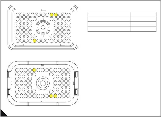
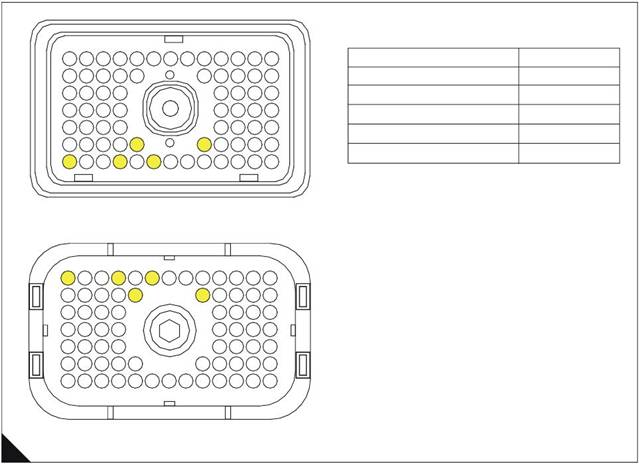
ECM terminal connections
Note: Using ECM connector P1.
4
13
23
31
12
22
30
11
21
29
10
20
28
9
19
8
7
6
5
18
4
17
27
3
16
26
2
15
25
1
14
24
Function
Ground
+ 8V
Pin Location
5
4
39
47
57
38
46
56
37 36
45 44
55 54 53
52
35
43
51
34
42
50
33 32
41 40
49 48
PWM input
66
70
69
68
67 66
65
64 63
62 61
60
59 58
Terminal side
57
47
31
70
69
68
67 66
36
65
64
63
62 61
60
59 58
48
40
24
23
13
12
11
10
9
>PEI<
8 7
6
5
4
3
2
1
14
B
Wire side
HA0024
117
![]()
![]()
![]() 4
4
2800 Series
Perkins Data Link circuit test
Test 45
Functional test
System operation
Use this procedure if the electronic service tool will not power up or communicate with the ECM through the
data link.
Background
The Perkins Data Link is the standard data link used by the ECM to communicate with electronic service tools
such as TIPSS-EST.
The ECM provides two data link connection terminals from the ECM machine harness connector J1, terminal-
9 (DATA LINK NEGATIVE) and terminal-8 (DATA LINK POSITIVE).
The OEM provides twisted pair wiring from the ECM to the data link connector.
Communication with the key switch OFF
With the key switch OFF, the ECM will not communicate with the electronic servic e tool. In order to avoid this
problem turn the key switch ON when working with the electronic service tool.
TIPSS-EST may indicate an error message that the ECM version is not recognized and the integrity of the
changed parameters and displayed data is not guaranteed. This will indicate that y ou have not installed the
latest release of the TIPSS-EST software or the ECM software is newer than the TIPSS-EST software.
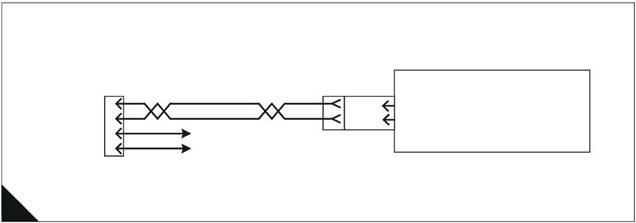
Perkins Data Link schematic
Note: Refer to the wiring diagrams for full connection details.
9 Pin
Perkins
D
E
Battery +
J1/8
J1/9
ECM
Perkins Data Link +
Perkins Data Link -
Data Link A
Connector B
Battery -
P1 J1
A
HA0025
118

![]() 2800 Series
2800 Series
Functional test
4
Test step
Test 45 - Perkins Data Link circuit test
Result
Action
Step 1: Check electrical connectors and wiring
Thoroughly inspect the ECM machine harness connector J1/
P1, data link connector, electronic service tool connectors and
cables, and the Perkins Data Link (terminals-8 and 9) in the
connectors.
Refer to "ECM terminal connections" on page 123.
Refer to Test 39: Inspecting electrical connectors on page
82.
Perform a 45 N (10 lb) pull test on each of the wires in the
connectors associated with the Perkins Data Link.
Check that the ECM connector Allen screw is correctly
tightened to not more than 3,0 Nm (2.2 lb ft) 0,31 kgf m.
Check the harness and wiring for abrasion and pinch points
from the sensor back to the ECM.
All connectors, pins and sockets are completely mated/
inserted and the harness/wiring is free of corrosion, abrasion
or pinch points.
Step 2: Determine the type of data link problem
Connect an electronic service tool to the data link connector.
Start the engine.
Result 1 - Engine starts and electronic service tool powers up
and communicates without error.
Result 2 - Engine starts and electronic service tool powers up
but displays an error.
Result 3 - Engine cranks but will not start regardless of the
condition of the electronic service tool.
Result 4 - Engine will not crank regardless of the condition of
the electronic service tool.
Result 5 - Engine starts but the electronic service tool does
not power up.
Note: To determine if the electronic service tool has powered up,
check the display screen or check the communication adapter
display. The electronic service tool will display information that
shows if the tool is getting power, and will be blank if it is not. If the
electronic service tool or the communication adapter powers up,
the data link connector is receiving power.
RESULT 1
RESULT 2
RESULT 3
RESULT 4
RESULT 5
Go to step 2.
Renew or repair wiring or
connectors as necessary.
Ensure all seals are correctly
installed and that connectors
are completely mated.
Check that the repair
eliminates the fault.
STOP.
There is not a problem with
the data link at this time.
If an intermittent condition
exists, thoroughly inspect all
wiring and connectors.
Refer to Test 39: Inspecting
electrical connectors on
page 82
STOP.
The electronic service tool
displays an error message.
The ECM is receiving battery
power.
Go to step 5.
Refer to Test 2: Engine
cranks but will not start on
page 38.
STOP.
Refer to Test 1: Engine will
not crank on page 37.
STOP.
The electronic service tool or
communications adapter
does not power up.
Ensure that the ECM is
receiving the correct battery
power.
Go to step 3.
119

![]() 4
4
2800 Series
|
Test step Result
Step 3: Check the battery voltage supply to the data link connector
Turn the key switch ON, engine OFF
Use a multimeter to measure the voltage from the data link
connector + BATTERY terminal to the - BATTERY terminal.
Refer to "Pin allocation for communications connector" on page
123.
Is the voltage is between 22.0 and 27.0 Volts for a 24 Volt
system ?
Step 4: Change electronic service tool components
If another engine or ECM is available connect the electronic RESULT 1
RESULT 2
Turn the key switch ON, engine OFF. Determine if the
electronic service tool operates correctly on the other engine. If
another engine is not available, find a different set of electronic
service tool cables.
Connect the electronic service tool to the data l ink connector
using the new cables.
Turn the key switch ON, engine OFF.
If changing cables allows the electronic service tool to operate
correctly, replace (one at a time) the pieces from the old cable
set into the one that does operate and repower the electronic
service tool each time to determine which piece is faulty.
If changing cables does not allow the electronic service tool to
operate correctly, connect a different electronic service tool.
Turn key switch to the ON, engine OFF.
Result 1 - The original electronic service tool works on
another engine.
Result 2 - A different electronic service tool works on the
original engine while the engine is being tested.
Action
The data link connector is
currently receiving the
correct voltage.
Go to step 4.
The data link connector is
not receiving the correct
voltage.
Inspect the wiring and fuses
to the connector.
Repair or renew the wiring or
batteries as required.
Check that the repair
eliminates the fault.
STOP.
Go to step 5.
Send the faulty electronic
service tool for repair.
STOP.
120

![]() 2800 Series
2800 Series
4
Test 45 - Perkins Data Link circuit test (Continued)
Test step Result
Step 5: Check battery voltage at the ECM
Ensure that the electronic service tool is connected to the data
link connector.
Disconnect the ECM machine harness connector J1/P1 and
insert a 70-terminal breakout T in series, or if signal reading
probes are available and ECM connector P1 is accessible
(without disconnecting), insert probes into terminal-52
(UNSWITCHED +BATTERY) and terminal-65 (-BATTERY).
Refer to "Breakout connector" on page 124.
Turn the key switch ON, engine OFF.
Measure the voltage between ECM connector PP terminal-52
(UNSWITCHED +BATTERY) and terminal-65 (-BATTERY).
Measure the voltage between P1 terminal-70 (KEY SWITCH)
and terminal-65 (- BATTERY).
The voltage, , is between 22.0 and 27.0 Volts with the key switch
ON ?
Step 6: Connect the electronic service tool directly to the ECM
Warnings!
Batteries give off flammable fumes which can explode. Do not
strike a match, cause a spark, or smoke in the vicinity of a
battery during the test procedure.
Do not connect the electronic service tool bypass harness to
the battery until the 20 Amp in-line fuse has been removed from
the +Battery line. If the fuse is not removed before connection
to the battery a spark may result.
Turn the key switch OFF, engine OFF.
Disconnect the ECM machine harness connector J1/P1 from
the ECM.
Install an electronic service tool power bypass cable. Connect
the bypass directly to the electronic service tool harness and
ECM. Refer to "Service tool bypass harness schematic" on
page 125.
Note: This bypass connects the key switch circuit directly to the
ECM. The ECM will remain powered until the connection to the
+BATTERY line is disconnected. Remove the 20 Amp fuse from
the in-line fuse holder to power down the ECM. Do not connect or
remove the bypass connections to the battery posts without first
removing the 20 Amp in-line fuse.
Is the electronic service tool operating correctly ?
Action
The ECM is currently
receiving the correct voltage.
Go to step 6.
The ECM is not receiving the
correct voltage.
Ensure that there is not an
aftermarket engine
protection switch overriding
battery power to the ECM.
Refer to Test 40: Electrical
power supply to the ECM on
page 88.
STOP.
There is a problem in the
machine wiring.
Re-insert the two data link
lines into the ECM connector
P1.
Contact the OEM for repair.
Check that the repair
eliminates the fault.
STOP.
Check that the 20 Amp fuse
in the bypass harness of the
electronic service tool is not
open (blown).
Go to step 7.
121

![]() 4
4
2800 Series
Test 45 - Perkins Data Link circuit test (Continued)
Test step Result
Step 7: Connect the electronic service tool and ECM to another battery
Warnings!
Batteries give off flammable fumes which can explode. Do not
strike a match, cause a spark, or smoke in the vicinity of a
battery during the test procedure.
Do not connect the electronic service tool bypass harness to
the battery until the 20 Amp in-line fuse has been removed from
the +Battery line. If the fuse is not removed before connection
to the battery a spark may result.
Connect the battery wires from the bypass harness of the
electronic service tool to a different battery not on the engine.
Refer to "Service tool bypass harness schematic" on page 125.
Does the electronic service tool operate correctly ?
Action
Refer to Test 40: Electrical
power supply to the ECM on
page 88.
STOP.
Temporarily connect a test
ECM. Repeat the test step.
If the problem is corrected
with the test ECM, and
returns when the old ECM is
connected, renew the ECM.
Check that the repair
eliminates the fault.
STOP.
122
![]() 2800 Series
2800 Series
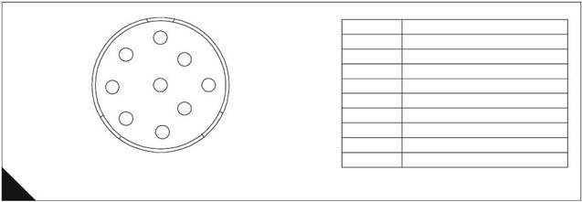
Pin allocation for communications connector
4
F
E
G
D
A
H
C
J
B
Pin No.
A
B
C
D
E
F
G
H
J
Description
Battery +
Battery -
CAN Bus Screen
Perkins Data Link +
Perkins Data Link -
J1939 CAN -
J1939 CAN +
J1922 Bus +
J1922 Bus -
B
Deutsch 9 Pin Perkins Data Link Connector
HA0027
ECM terminal connections
Note: Using ECM connector P1.
13
23
31
12
22
30
11
21
29
10
20
28
9
19
8
7
6
5
18
4
17
27
3
16
26
2
15
25
1
14
24
Function
Perkins Data Link +
Perkins Data Link -
Pin Location
8
9
39
47
57
38
46
56
37 36
45 44
55 54 53
52
35
43
51
34
42
50
33 32
41 40
49 48
70
69
68
67 66
65
64
63
62 61
60
59 58
Terminal side
57
47
31
70
69
68
67 66
36
65
64
63
62 61
60
59 58
48
40
24
23
13
12
11
10
9
>PEI<
8 7
6
5
4
3
2
1
14
C
Wire side
HA0026
123
![]() 4
4
Breakout connector
Note: Using ECM connector P1.
2800 Series
13
12
11
10
9
8
7
6
5
4
3
2
1
Function
Pin Location
23
22
21 20
19
18
17
16
15
14
Unswitched Battery +
52
31
39
47
57
70
30
38
46
56
69
29 28
37 36
45 44
55 54
68 67
53
66
65
64
63
52
62
27 26
35 34
43 42
51 50
61 60
25 24
33 32
41 40
49 48
59 58
Unswitched Battery +
Key switch
Battery -
Battery -
53
70
67
65
Terminal side
57
47
31
23
70
69
68
67
66
36
65
64
63
62
61
60
59
58
48
40
24
14
13
12
11
10
9
>PEI<
8 7
6
5
4
3
2
1
D
Wire side
HA0028
124
![]() 2800 Series
2800 Series
Service tool bypass harness schematic
4
Red
Black
20 Amp
In line Fuse
J1/70
Key Switch
ECM
Unswitched Battery +
Battery -
Perkins Data Link +
Perkins Data Link -
J1922 Data Link -
J1922 Data Link +
J1939 Data Link +
J1939 Data Link -
J1939 Data Link Screen
A
B
D
E
J
H
G
F
C
9 Pin
J1/52
J1/53
J1/65
J1/67
J1/8
J1/9
J1/1
J1/14
J1/34
J1/50
J1/42
J1
Unswitched Battery +
Unswitched Battery +
Battery -
Battery -
Perkins Data Link +
Perkins Data Link -
J1922 Data Link -
J1922 Data Link +
J1939 Data Link +
J1939 Data Link -
J1939 Data Link Screen
Perkins Data Link
Connector
E
HA0029
125
![]()
![]()
![]()
![]() 4
4
2800 Series
Engine speed/timing circuit test
Test 46
Diagnostic codes
System operation
Functional test
Use this procedure to diagnose the system only when there is an active or easily repeated diagnostic code that
is associated with either the crankshaft or camshaft position sensor circuit or if you have been referred to this
test from a diagnostic procedure without a diagnostic fault code.
The engine uses two engine speed/timing sensors. One sensor picks up the camshaft gear and the other the
crankshaft gear. Both detect engine speed and timing reference from a unique pattern on the gear. The ECM
counts the time between pulses created by the sensor as the gear rotates in order to determine rev/min.
Under normal operation, the camshaft position sensor is used to determine timing (when the piston in cylinder
number 1 is at the top of the compression stroke) for starting purposes. When the timing has been established,
the crankshaft position sensor is then used to determine engine speed and the camshaft position sensor signal
is ignored.
After locating No. 1 cylinder, the ECM triggers each injector in the correct firing order and at the correct time.
The actual timing and duration of each injection is based on engine rev/min and load. If the engine is running
and the signal from the crankshaft position sensor is lost, a slight change in engine performance will be noticed
when the ECM switches to the camshaft position sensor.
Loss of the camshaft position sensor signal during engine operation will not result in any noticeable change in
engine performance. However, if the camshaft position sensor signal is not present during start-up the engine
may take slightly longer to start, or may run rough for a few seconds until the ECM determines the correct firing
order by using the crankshaft position sensor only.
The engine will start and run when only one sensor signal is present from either of the sensors. The loss of the
signal from both sensors will result in the ECM terminating injection and shutting down the engine, or
preventing it from starting.
Both sensors are magnetic with a connector on a "flying lead’.
Caution: The two sensors are not interchangeable, do not switch sensor positions.
If the sensors are replaced a timing calibration is NOT necessary for the engine.
Note: Timing calibration is only necessary after replacing an ECM that will not communicate.
If the ECM is replaced, it will be necess ary to do a Timing Calibration.
The crankshaft position sensor is connected to the ECM through the engine harness connector J2/P2 terminal-
48 (CRANK SPEED/TIMING POSITIVE) and terminal-49 (CRANK SPEED/TIMING NEGATIVE).
The camshaft position sensor is connected to the ECM through engine harness connector J2/P2 terminal-58
(CAM SPEED/TIMING POSITIVE) and terminal-59 (CAM SPEED/TIMING NEGATIVE).
126
![]() 2800 Series
2800 Series
When installing the sensors
Lubricate the O-ring with oil.
Ensure that the sensor has a connector face seal inside the connector body. If a seal is damaged or
missing, replace the seal.
Ensure that the sensor is fully seated into the engine before tightening the bracket bolt.
Ensure that the connector is latched on both sides.
Ensure that the harness is correctly secured and the tie-wraps are placed in the correct location.
Speed/timing sensors schematic
Note: Refer to the wiring diagrams for full connection details.
4
A
|
|
Return 1
J401 P401
Camshaft Position Sensor
Return 1
J402 P402
J2/48
J2/49
J2/58
J2/59
P2 J2
ECM
Crank Speed Timing +
Crank Speed Timing -
Cam Speed timing +
Cam speed timing -
HA0030
127
|
Diagnostic codes
2800 Series
Engine response
128

![]() 2800 Series
2800 Series
Functional test
4
Test 46 - Engine speed/timing circuit test
Test step Result
Step 1: Connect an electronic service tool and note all active and logged diagnostic codes
Action
Connect the electronic service tool to the data link connector.
Turn the key switch ON, engine OFF.
Check for one of the following logged or active diagnostic
codes:
261-13 Camshaft Sensor To Crank Sensor Calibration
342-12 Loss Of Engine Cam Sensor rev/min Signal
190-12 Loss Of Engine Crank Sensor rev/min Signal
Notes:
If the diagnostic code is logged but not active, run the engine
until it is at normal operating temperature. The problem may
only occur when the engine is at the normal operating
temperature. If the engine will not start monitor the engine rev/
min from the electronic service tool while cranking the engine.
The electronic service tool may need to be powered from
another battery while cranking the engine to ensure that the
electronic service tool does not reset.
If there are occurrences of the 342-12 and 190-12 faults refer
to Test 39: Inspecting electrical connectors on page 82.
If you have been referred here from a diagnostic procedure
without a diagnostic fault code because engine rev/min was
not indicated on an electronic service tool select NO ENGINE
REV/MIN.
Are any of the diagnostic codes listed above logged or
active ?
Step 2: Check Sensors and Bracket Installation
Note: To ensure correct operation the sensor flange should be
flush against the engine.
Inspect the bracket to ensure that the installation allows the
sensor flange to be flush against the engine. Check that the
bracket is not bent. Refer to "Speed/timing sensors schematic"
on page 127. The bracket cannot be replaced separately.
Ensure that one O-ring has been installed on the sensor, and
that it is free of damage.
If a 261-13 Camshaft Sensor To Crank Sensor Calibration
diagnostic code is active, there may be a problem with the
assembly of the engine.
Are the sensors and the bracket are correctly installed ?
342-12, 190-12 or
261-13
NO CODE
NO ENGINE REV/
MIN
There is an active or logged
diagnostic code.
Go to step 3.
If none of the codes listed
are active or logged and the
engine is not running
correctly, refer to the
appropriate symptoms in
"Diagnostic procedures
without a diagnostic fault
code" on page 36.
STOP.
Engine rev/min is not
indicated on an electronic
service tool.
Go to step 2.
The sensors and the bracket
are correctly installed.
Go to step 3.
Loosen the bolt holding the
sensor bracket to the
engine.
Seat the sensor and tighten
the bolt. If the sensor will not
seat, repair or replace the
sensor as necessary. The
sensor must not be removed
from the bracket.
Ensure that the sensor is
correctly oriented and the
harness is secured in the
correct location.
STOP.
129

![]() 4
4
2800 Series
Test 46 - Engine speed/timing circuit test (Continued)
Test step Result
Step 3: Measure the sensor resistance through the engine harness
Turn the key switch OFF, engine OFF.
Thoroughly inspect ECM engine harness connector J2/P2.
Refer to Test 39: Inspecting electrical connectors on page 82.
Perform a 45 N (10 lb) pull test on ECM engine harness
connector P2 terminals-48, 49, 58 and 59. Refer to "ECM
terminal connections" on page 132.
Ensure that connector latching tab is correctly latched and is in
the fully latched position.
Check that the ECM connector All en screw is correctly
tightened to not more than 3,0 Nm (2.2 l b ft) 0,31 kgf m.
Repair the harness or connector if a problem is found.
Ensure that the wiring harness is correctly routed and secured
at the correct locations.
Note: Ensure that the wiring harness is not pulled too tight causing
intermittent connections when vibration or movement occurs.
Inspect the sensor harness wiring for cuts and abrasions.
If the harness and the connector are OK, disconnect engine
harness ECM connector J2/P2.
Use a multimeter to measure the sensor resistance (Ohms)
from engine harness connector P2 as indicated below. Move
the harness (pull/shake the wires, especially directly behind the
sensors) while taki ng a measurement to check for an
intermittent open or short circuit. Refer to "ECM terminal
connections" on page 132.
Crankshaft position sensor - The resistance from P2 terminal-48
(CRANK SPEED/TIMING POSITIVE) and terminal-49 (CRANK
SPEED/TIMING NEGATIVE) is between 75.0 and 230.0 Ohms.
Camshaft position sensor - The resistance from P2 terminal-58
(CAM SPEED/TIMING POSITIVE) and terminal-59 (CAM SPEED/
TIMING NEGATIVE) is between 600 and 1800 Ohms.
Do the readings agree with the values listed above ?
Action
The engine harness and
sensor do not indicate a
short or open circuit.
Go to step 5.
The sensor resistance is not
within the acceptable range
when measured through the
engine harness.
Go to step 4.
130

![]() 2800 Series
2800 Series
4
Test 46 - Engine speed/timing circuit test (Continued)
Test step Result
Step 4: Measure sensor resistance at the sensor
Turn the key switch OFF, engine OFF.
Check the harness and wiring for abrasion and pinch points
from the sensor back to the ECM.
Disconnect the suspect sensor from the engine harness as
described below.
Thoroughly inspect ECM engine harness sensor connector
J401/P401 or J402/P402. Refer to Test 39: Inspecting
electrical connectors on page 82 for details.
Use a multimeter to measure the sensor resistance (Ohms) at
the sensor connector between terminal-A and terminal-B.
Crankshaft position sensor - The resistance from J401 terminal-
2 (CRANK SPEED/TIMING POSITIVE) and J401 terminal-1
(CRANK SPEED/TIMING NEGATIVE) is between 75.0 and 230.0
Ohms.
Camshaft position sensor - The resistance from J402 terminal-2
(CAM SPEED/TIMING POSITIVE) and J402 terminal-1 (CAM
SPEED/TIMING NEGATIVE) is between 600 and 1800 Ohms.
Note: Timi ng calibration is not necessary fol lowing replacement of
the Crankshaft Position or camshaft position sensor. Refer to
"When installing the sensors" on page 127.
Do the readings agree with the values that are listed above ?
Step 5: Install engine speed/timing bypass harness
Ensure the key switch is OFF, engine OFF.
Disconnect engine harness ECM connector J2/P2 (if not
already disconnected).
For the crankshaft position sensor - install 16 AWG
wires from J2/P2 terminal-48 to P401 terminal-2 and from
J2/P2 terminal-49 to P401 terminal-1.
For the camshaft position sensor - install 16 AWG wires
from J2/P2 terminal-58 to P402 terminal-2 and from J2/P2
terminal-59 to P402 terminal-1.
Reconnect the engine harness connector J2/P2.
Start the engine to determine if the bypass harness repairs the
problem.
Is the problem corrected with the bypass installed ?
Action
The sensor resistance i s
correct.
Go to step 5.
The sensor resistance is out
of range, obtain a new
sensor.
Before installing the new
sensor, measure the
resistance of the new sensor
as outlined in the test step
using the same test setup
(test harness, multimeter
and meter settings). If the
new sensor is in range,
install the new sensor in the
engine.
Loosen the bolt holding the
sensor bracket to the
engine. Ensure the O-ring is
installed and free of
damage. Seat the sensor
and tighten the bol t.
If the sensor will not seat,
repair or replace the sensor,
as necessary.
The sensor must not be
removed from the bracket.
Ensure that the sensor is
correctly oriented and the
harness is secured in the
correct location.
STOP.
Permanently install a new
harness section.
STOP.
Double check to ensure that
the correct terminals have
been installed in the correct
location of the ECM engine
harness connector P2.
If the temporary harness
was installed correctly,
install the original wiring.
Go to step 6.
131

![]() 4
4
2800 Series
Step 6: Check the ECM
Test 46 - Engine speed/timing circuit test (Continued)
Test step Result
Action
Turn the key switch OFF, engine OFF.
Temporarily connect a test ECM.
Start the engine and run it to repeat the conditions when the
problem occurs. Determine if the problem is corrected with the
test ECM.
If the problem does not return with the test ECM, reinstall the
suspect ECM and ensure that the problem returns.
Does the problem remain with the suspect ECM ?
If the test ECM works and
the suspect ECM does not,
replace the ECM.
STOP.
Replace the sensor and
ensure that the problem is
corrected.
STOP.
ECM terminal connections
Note: Using ECM connector P2.
13
12
11
10
9
8
7
6
5
4
3
2
1
Function
Pin Location
23
22
21
20 19
18
17
16
15
14
Crank Speed/Timing Signal +
48
31
30
29 28
27
26
25
24
Crank Speed/Timing Signal -
49
39
47
38
46
37 36
45 44
35 34
43 42
50
33
41
49
32
40
48
Cam Speed/Timing Signal +
Cam Speed/Timing Signal -
58
59
57
56 55
54
53
52
51
70 69
68
67
66
65 64 63
62
61
60 59
58
Terminal side
57
47
31
70 69
68
67
66
36
65
64 63
62
61
60 59
58
48
40
24
23
13
12
11
10
9
>PEI<
8 7
6
5
4
3
2
1
14
B
Wire side
HA0031
132
![]() 2800 Series
2800 Series
Speed and timing sensors
1 Crankshaft speed and timing s ensor
2 Mounting bracket
3 Cable connection
Note: This is not a connector. Do not try to disassemble.
4 Connector
5 Camshaft speed and timing sensor
4
3
2
1
3
2
5
4
4
C
HA0032
133
![]()
![]()
![]()
![]() 4
4
2800 Series
Engine speed/timing calibration
Test 47
Diagnostic codes
Special tools
Functional test
|
Part Number |
Description |
|
GE50038 |
Timing calibration probe |
|
GE50040 |
Harness adapter for deutsch “DT” timing probe connection |
|
GE50039 |
Timing calibration probe adapter sleeve |
|
CH11148 |
Engine turning tool |
System operation
Use this procedure if diagnostic code 261-13 Check Timing Sensor Calibration is present, if the ECM has been
replaced or if work has been done to the engine front drive train.
The crankshaft position sensor provides an engine speed signal (rev/min) to the ECM. The signal is created
as the crankshaft gear rotates past the pickup of the crankshaft position sensor. The camshaft position sensor
provides the timing signal to the ECM. The signal is created as the camshaft gear rotates past the pickup of
the camshaft position sensor. A unique pattern on the gear allows the ECM to determine the crankshaft
position and when the cylinder number one piston is at the top of the compression stroke. In the event that the
signal is lost from one of the sensors, a diagnostic code is generated. The ECM then uses special logic to allow
the engine to start and run on only one sensor.
If the ECM requires replacement or if work has been performed on the front drive train, a timing calibration
mus t be performed.
Timing calibration is accomplished by installing a special magnetic pickup into the side of the engine block.
The magnetic pickup senses a spec ial slot on the crankshaft counterweight. The magnetic pickup is then
connected to the ECM through the engine harness speed/timing calibration connector P400, while the engine
is running.
In order to carry out a timing calibration, the engine must be running at 1100 rev/min. Since this speed is not
within the range of the normal speed setting controls, proceed as follows:
1 Set the "Digital Speed Control Installed" to "Not Installed" from the TIPSS-EST configuration screen.
2 If an analogue speed control is fitted, select PWM speed control in the "Desired Speed Input Arrangement"
option on the configuration screen. If a PWM speed control is fitted, select Analogue speed control in the
"Desired Speed Input Arrangement" on the configuration screen.
Note: If both analogue and PWM speed inputs are connected, one must be disconnected and the associated
speed control selected.
3 If the engine is now run, it should run up to 1100 rev/min and timing calibration can be carried out.
4 After completion of the timing calibration, ensure that all parameters are returned to their original values.
Note: Timing calibration will not increase or decrease the available engine power. Do not c alibrate the engine
timing expecting an increase in engine power.
134
![]() 2800 Series
2800 Series
Timing calibration
1 GE50038 TC probe
2 Slot
3 Counterweight
4
Diagnostic codes
|
Diagnostic fault code |
Conditions that could cause the code |
System response |
To find the fault |
|
261-13 |
Check Timing Sensor Calibration Timing has not been calibrated since the ECM was installed or the calibration is out of specification more than the ECM will allow. |
Electronic system response The ECM uses default timing. Timing can be out of specification by as much as 4°. Engine response The engine may run rough, emit white smoke in the exhaust or there may not be any noticeable performance effect. |
Proceed with Test 47: Engine speed/ timing calibration. |
135
 4
4
Functional test
2800 Series
Test 47 - Engine speed/timing calibration
Test step Result
Step 1: Install the timing adapter group
Turn the key switch OFF, engine OFF
Use the turni ng tool to put either the No. 1 or No. 6 piston at top
centre. After locating top centre, rotate the engine back (rotate
the engine in opposite direction of correct engine rotation) 60°.
Remove the timing calibration plug from the left side of the
engine and install the timing probe adapter sleeve into the hol e
for the plug.
Step 2: Install GE50038 TC probe on the engine
Caution: If the crankshaft is not in the correct position when the
timing probe is installed, the timing probe will be damaged when
the engine is started.
Put a 2D-6392 O-ring on the end of the magnetic pickup sensor
(a small amount of clean engine oil wil l allow the seal to slide
onto the sensor more easily).
Push the sensor through the adapter until it comes in contact
with the outermost portion of the crankshaft counterweight.
Move the O-ring downward against the adapter.
Withdraw the magnetic transducer 1,0 mm (0.04 in) and hand
tighten the nut on the adapter sleeve in order to secure the
magnetic pickup in place.
Connect the GE50038 timing probe to the GE50040 Deutsch
DT timing harness adapter.
Step 3: Start engine and allow coolant to reach operating temperature
Start the engine and run until the engine has warmed up
enough to exit cold mode operation. The electronic service tool
"Status" screen will display “COLD MODE” in the upper corner
when cold mode operation exists.
Check for ACTIVE diagnostic codes. Use the procedures in this
manual to diagnose and repair any ACTIVE diagnostic codes
before attempting a calibration check. The engine must not
have any diagnostic fault conditions present during the timing
calibration, other than 261-13 Check Timing Sensor
Calibration.
Stop the engine.
Step 4: Connect an electronic service tool
Connect an electronic service tool to the data link connector.
Follow the procedure in "System operation" on page 134 so
that the engine will run at 1100 rev/min.
Access the "Timing Calibration" screen located under the
"Service\Calibrations" menu on TIPSS-EST.
Note: To perform a timing calibration, the engine rev/min must be
held as steady as possible at approximately 1100 rev/min. Any
changes to engine rev/min (greater than 100 rev/min) will slow
down the procedure and reduce accuracy. The correct engine
speed is set using the procedure described "System operation" on
page 134.
Connect the GE50040 Deutsch DT adapter harness for the
GE50038 timing probe to the speed/timing calibration
connector P400.
Be certain that all connections (TC Probe, electronic service
tool, etc) are made correctly.
Start the engine
Action
Go to step 2.
Go to step 3.
Go to step 4.
Go to step 5.
136

![]() 2800 Series
2800 Series
4
Test 47 - Engine speed/timing calibration (Continued)
Test step Result
Step 5: Calibrate the speed/timing sensor
To calibrate the timing to the correct setting select Continue on
the electronic service tool and wait until the electronic service
tool indicates that the timing is CALIBRATED.
Note: If the electronic service tool display reads CALIBRATION
UNSUCCESSFUL, the electronic injection timing has not been set.
Re-check the tool installation and tool operation and try again
to calibrate electronic injection timing. If the crankshaft and
camshaft gears have been reassembled incorrectly (relative to
each other), the engine will not calibrate.
If the timing calibration has been successfully completed, do
not exit the Timing Calibration Screen on the electronic service
tool until you have disconnected the timing probe from the
speed/timing calibration connector P400.
Was the timing calibration procedure completed
successfully ?
Action
The timing calibration
procedure was completed
successfully.
Go to step 6.
Check that the engine rev/
min was stable during the
testing (+/- 50 rev/min).
If the engine rev/min was
unstable or could not be
controlled within +/- 50 rev/
min because of mechanical
or electrical factors, refer to
Test 3: Engine misfires, runs
rough or is unstable on page
39.
If all of the checks are OK
but the timing still will not
calibrate, check the timing
probe cable and timing
probe to ensure it is not bent.
If it is not bent, restart this
procedure.
|
|
|
|
Disconnect the timing probe from the speed/timing calibration Go to step 7.
Exit the electronic service tool "Timing Calibration" screen. installed following exit of the
electronic service tool
Timing Calibration Screen,
engine speed diagnostic
codes may be generated
and should be cleared.
STOP.
Step 7: Restore correct engine speed
Use TIPSS-EST to restore the correct digital, analogue or STOP.
Run the engine to check the correct running speed. selection.
137
![]()
![]()
![]()
![]() 4
4
2800 Series
Injector solenoids circuit test
Test 48
Diagnostic codes
System operation
Functional test
Use this procedure if a 1-11, 2-11, 3-11, 4-11, 5-11, 6-11 Cylinder Fault is present or is you have been referred
here after following the sequence of steps in Test 3: Engine misfires, runs rough or is unstable on page 39, or
Test 4: Low power/poor or no response to throttle on page 40.
It is important to perform this procedure when the injector is under identical conditions as when the problem
occurs. Typically, injector solenoid problems occur when the engine is warmed up and/or when the engine is
under vibration (heavy loads).
The 2300 and 2800 Series engines utilize electronic unit injectors that are mechanically actuated and
electronically energized.
The injectors can be individually cut out while the engine is running to check for weak cylinders, or tested
without the engine running to check for electrical circuit problems.
The injector solenoid is mounted on top of the fuel injector body along side the rocker arm return spring.
Injector Trim Codes provide a means to fine tune each individual injector for optimum performance. A 268-02
Check Programmable Parameters diagnostic code will be active if the injector codes are not programmed.
If the ECM is replaced, all six injector codes must be programmed into the new ECM.
Injector schematic
Note: Refer to the wiring diagrams for full connection details.
Injector
Cyl 1
Injector
Cyl 2
Injector
Cyl 3
Injector
Cyl 4
Injector
Cyl 5
Injector
Cyl 6
|
|
6
10
3
11
12
1
J300 P300
|
J2/45
J2/46
J2/54
J2/39
J2/38
J2/37
J2/36
P2 J2
|
Injector Common Cylinders 1 & 2
Injector Common Cylinders 3 & 4
Injector Common Cylinders 5 & 6
Injector Cylinder 6
Injector Cylinder 5
Injector Cylinder 4
Injector Cylinder 3
Injector Cylinder 1
A
HA0034
138

|
Diagnostic codes
4
lamp ON and log the diagnostic
code. If the cause of the diagnostic
48: Injector
solenoids circuit
cylinders will be affected because
Functional test
Test step
Test 48 - Injector solenoids circuit test
Result
Action
Step 1: Inspect electrical connectors and wiring
Turn key switch OFF, engine OFF
Warning! Ensure that the key switch is OFF. Possible strong
electrical shock hazard if the key switch is not turned OFF.
Thoroughly inspect the ECM engine harness connector J2/P2
and the injector solenoids connector.
Perform a 45 N (10 lb) pull test on each of the wires in the ECM
connector and the injector solenoids connector.
Check that the ECM connector Allen screw is correctly
tightened to not more than 3,0 Nm (2.2 lb ft) 0,31 kgf m.
Check the injector solenoids connector to ensure that it is
correctly mated.
Check the harness and wiring for abrasion and pinch points
from the injector(s) back to the ECM.
Are connectors/pins/sockets completely mated/inserted, and
the harness/wiring free of corrosion, abrasion or pinch
points ?
Step 2: Check for logged injector solenoid diagnostic codes
Connect an electronic service tool to the data link connector.
Turn the key switch ON, engine OFF
Access the screen displaying logged diagnostic codes
Does the service tool indicate a logged 1-11, 2-11, 3-11, 4-11,
5-11 or 6-11 cylinder fault ?
Go to step 2.
Repair or replace wiring or
connectors as necessary.
Ensure all seals are correctly
installed and that connectors
are completely mated.
Check that the repair
eliminates the fault.
STOP.
Go to step 4.
Go to step 3.
139

![]() 4
4
2800 Series
Test 48 - Injector solenoids circuit test (Continued)
Test step Result
Step 3: Check cylinder to cylinder variation of injectors
Connect the TIPSS-EST to the data link connector.
Start the engine.
Allow the engine to warm up to normal operating temperature -
77 °C (171 °F).
Access the Cylinder cut-out test located under the
"Diagnostics\Diagnostic Tests" menu.
Select the start button at the bottom of the "Cylinder cut-out"
test screen.
Do all cylinders indicate OK on the TIPSS-EST screen?
Step 4: Check injector solenoids using the TIPSS-EST Injector Solenoid test
Start the engine.
Allow the engine to warm up to normal operating temperature -
77 °C (171 °F)
Turn the key switch OFF, engine OFF
Connect an electronic service tool at the data link connector.
Turn the key switch ON, engine ON
After the engine is warmed to operating temperature, access
and begin the Injector Solenoid test located under the
"Diagnostics\Diagnostic Tests" menu of the electronic service
tool.
Note: Do not confuse the Injector Solenoid test with the Cylinder
cut-out test. The Cylinder cut-out test is used to shut off fuel to a
specific cylinder while the engine is running. The Injector Solenoid
test is used in order to actuate the injector solenoids in order to
"hear" the injector solenoids click, when the engine is not running,
to determine that the circuit is functioning correctly.
Perform the Injector Solenoid test two or three times.
Do all cylinders indicate OK ?
Action
All cylinders test OK.
If a misfiring problem or low
power problem still exists
refer to Test 3: Engine
misfires, runs rough or is
unstable on page 39 or Test
4: Low power/poor or no
response to throttle on page
40.
If a diagnostic code results
from running the Cylinder
cut-out test then Go to step
4.
Go to step 4.
There is not an electronic
problem with the injectors at
this time.
If the Cylinder cut-out test
returned a NOT OK for any
injector, refer to Test 3:
Engine misfires, runs rough
or is unstable on page 39.
STOP.
Note the cylinders that
indicate OPEN and/or
SHORT.
Go to step 5.
|
Turn key switch OFF, engine OFF Go to step 7.
electrical shock hazard if the key switch is not turned OFF. indicating the short circuit.
Disconnect the injector solenoids connector J300/P300 Go to step 6.
Turn the key switch ON, engine OFF
Perform the Injector Solenoid test two or three times.
Do all cylinders indicate OPEN ?
140

![]() 2800 Series
2800 Series
4
Test 48 - Injector solenoids circuit test (Continued)
Test step Result
Step 6: Check ECM for short circuits using service tool Injector Solenoid test
Turn key switch OFF, engine OFF
Warning! Ensure that the key switch is OFF. Possible strong
electrical shock hazard if the key switch is not turned OFF.
Disconnect ECM engine harness connector J2/P2 from the
ECM and check for evidence of moisture entry.
Turn the key switch ON, engine OFF
Perform the Injector Solenoid test two or three times.
Note: With the engine harness disconnected all of the +5 V
supplied sensor open circuit diagnostic codes will be active. This is
normal. Clear all of these diagnostic codes after completing this
test step.
Do all cylinders indicate OPEN with engine harness connector
P2 disconnected from the ECM ?
Action
The short circuit is in the
engine harness.
Repair or replace the engine
harness as required.
Clear all diagnostic codes
after completing this test
step.
STOP.
Temporarily connect
another ECM.
Repeat this test step. If the
problem is resolved with the
new ECM, reconnect the old
ECM to check that the
problem returns with the old
ECM.
If the new ECM works and
the old one did not, renew
the ECM.
STOP.
|
|
|
|
|
|
|
|
|
|
|
Turn key switch OFF, engine OFF If the previous step indicated
Disconnect injector solenoids connector J300/P300. but the injector sharing the
Turn the key switch ON, engine OFF injector common indicates a
Make a jumper wire 100 mm (4 in) long with a Deutsch Pin on
both ends. Go to step 9.
Insert the jumper wire between the injector common socket of If the previous step indicated
the problem injector, and the problem injector socket of the two injectors sharing an
injector solenoids connector P300. For example, if injector 5 is injector common are open.
Perform the Injector Solenoid test two or three times. injector common are short.
Go to step 8.
Repeat this test for each suspect injector. Ensure that the
Injector Solenoid test is disabled before handling the jumper
wires.
141

![]() 4
4
2800 Series
Test 48 - Injector solenoids circuit test (Continued)
Test step Result
Step 8: Check ECM for open circuit
Turn key switch OFF, engine OFF
Warning! Ensure that the key switch is OFF. Possible strong
electrical shock hazard if the key switch is not turned OFF.
Disconnect the engine harness from the ECM connector J2
and connect a 70-terminal breakout T to the ECM (do not
connect the engine harness to the breakout T).
Use a jumper wire to short between the injector socket and the
injector common socket of the suspect injector.
Perform the Injector Solenoid test two or three times.
Note: With the engine harness disconnected all of the +5 V
supplied sensor open circuit diagnostic codes will be active. This is
normal. Clear all of these diagnostic codes after completing this
test step.
Does the cylinder with the jumper wire installed indicate
SHORT ?
Step 9: Check injector harness under valve cover
Turn key switch OFF, engine OFF
Warning! Ensure that the key switch is OFF. Possible strong
electrical shock hazard if the key switch is not turned OFF.
Remove the valve cover to gain access to the problem
injector(s).
Disconnect the harness from the problem injector and from the
other injector sharing the same inj ector common.
Thoroughly clean the terminals of both injectors and the
harness. Exchange the harness between the two injectors
sharing the common.
Turn key switch ON, engine OFF
Perform the Injector Solenoid test two or three times.
Did the problem change to the other injector with the
movement (exchanging terminals) of the harness ?
Step 10: Check engine harness under valve cover for an open circuit in the common
Turn key switch OFF, engine OFF
Warning! Ensure that the key switch is OFF. Possible strong
electrical shock hazard if the key switch is not turned OFF.
Remove the valve cover to gain access to the problem
injector(s).
Disconnect each of the injectors i ndi cating an OPEN from the
wiring harness. Ensure that each of the connectors from the
disconnected injector harness does not touch other
components and short to ground.
Attach a jumper wire to both terminals of the injector harness
for the two injectors shari ng an injector common.
Turn key switch ON, engine OFF
Perform the Injector Solenoid test two or three times.
Do both cylinders with the short in place indicate an OPEN ?
Action
The ECM is OK. Replace or
repair the engine harness.
STOP.
Temporarily connect
another ECM.
Repeat this test step. If the
problem is resolved with the
new ECM, reconnect the old
ECM to check that the
problem returns with the old
ECM.
If the new ECM works and
the old one did not, renew
the ECM.
STOP.
Replace the faulty injector
indicating the problem.
Restore the wiring to the
correct injector(s).
STOP.
Replace the injector harness
under the valve cover.
STOP.
Replace the engine harness
under the valve cover.
Check new harness
installation using the Injector
Solenoid test before
installing the valve covers.
STOP.
BOTH injectors indicate
SHORT.
Replace BOTH injectors.
STOP.
142

![]() 2800 Series
2800 Series
4
Test 48 - Injector solenoids circuit test (Continued)
Test step Result
Step 11: Check engine harness under valve cover for short circuits in the injector wires
Action
Turn key switch OFF, engine OFF
Warning! Ensure that the key switch is OFF. Possible strong
electrical shock hazard if the key switch is not turned OFF.
Remove the valve cover to gain access to the problem
injector(s).
Disconnect each of the injectors indicating an SHORT from the
wiring harness. Ensure that each of the connectors from the
disconnected injector harness does not touch other
components and short to ground.
Turn key switch ON, engine OFF
Perform the Injector Solenoid test two or three times.
Do both cylinders indicate an OPEN ?
Step 12: Check for a short circuit in the injector common to the engine
Turn key switch OFF, engine OFF
Warning! Ensure that the key switch is OFF. Possible strong
electrical shock hazard if the key switch is not turned OFF.
Disconnect the ECM engine harness connector J2/P2.
Measure the resistance from the problem injector common
terminal of connector P2 to the engine ground stud.
Does the multimeter indicates resistance greater than 10
Ohms ?
Step 13: Check for a short circuit in the injector
Turn key switch OFF, engine OFF
Warning! Ensure that the key switch is OFF. Possible strong
electrical shock hazard if the key switch is not turned OFF.
Reconnect one of the two disconnected injectors.
Turn key switch ON, engine OFF
Perform the Injector Solenoid test two or three times.
Does the reconnected injector indicates a SHORT ?
Step 14: Check for a short circuit in the other injector
Turn key switch OFF, engine OFF
Warning! Ensure that the key switch is OFF. Possible strong
electrical shock hazard if the key switch is not turned OFF.
Reconnect the other disconnected injector.
Turn key switch ON, engine OFF
Perform the Injector Solenoid test two or three times.
Does the reconnected injector indicates a SHORT ?
Leave the injector wi res
disconnected.
Neither of the injector wires
are shorted to the engine.
Go to step 12.
Replace the injector harness
under the valve cover.
STOP.
Reconnect the engine
harness to the ECM.
Go to step 13.
Replace the injector harness
under the valve cover.
STOP.
Replace the injector.
STOP.
This injector is OK.
Go to step 14.
Replace the injector.
STOP.
This injector is OK.
STOP.
143
![]() 4
4
ECM terminal connections
Note: Using ECM connector P2.
2800 Series
13
12
11
10
9
8
7
6
5
4
3
2
1
Function
Pin Location
23
22
21
20 19
18
17
16
15
14
Injector Common Cyls 1 & 2
44
31
30
29 28
27
26
25
24
Injector Common Cyls 3 & 4
45
39
47
57
38
46
56
37 36
45 44
55 54
53
52
35 34
43 42
51 50
33
41
49
32
40
48
Injector Common Cyls 5 & 6
Injector Cylinder 1
Injector Cylinder 2
46
36
37
70 69
68
67
66
65 64
63
62
61
60 59
58
Injector Cylinder 3
Injector Cylinder 4
Injector Cylinder 5
38
39
54
57
47
31
23
70 69
13 12
68
11
Terminal side
67 66 65 64 63 62
36
>PEI<
10 9 8 7 6 5
61
4
60 59
3 2
58
1
48
40
24
14
Injector Cylinder 6
55
B
Wire side
HA0036
144
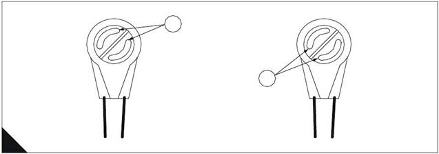
![]() 2800 Series
2800 Series
Engine harness injector connector
4
Pin No.
1
2
3
5
6
7
10
11
12
Function
Injector Cylinder No. 1
Injector Cylinder No. 3
Injector Cylinder No. 5
Injector Common Cylinders 1 and 2
Injector Common Cylinders 5 and 6
Injector Common Cylinders 3 and 4
Injector Cylinder No. 6
Injector Cylinder No. 4
Injector Cylinder No. 2
12
11
10
9
8
7
1
2
3
4
5
6
C
HA0037
Electronic unit injector harness terminals
1
2
D
HA0038
1 Attach jumper wire #1 here
2 Attach jumper wire #2 here
145
![]()
![]()
![]()
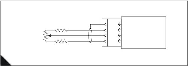
![]() 4
4
2800 Series
Analogue sensor abnormal test
Test 49
Diagnostic codes
System operation
Functional test
Use this procedure to diagnose an "Abnormal" diagnostic code for the analogue speed control.
The analogue speed control may be a simple potentiometer or may be a signal from a device such as a load
sharing/synchronising controller. The actual analogue speed control device is not supplied by Perkins, it is an
optional control supplied by the OEM.
Analogue speed control schematic
Note: Refer to the wiring diagrams for full connection details.
680R
J1/67
- Battery
ECM
5K Analogue
Speed Setting
Potentiometer or
Input from Load
Sharer/Synchroniser
680R
J1/3
J1/15
J1/2
Analogue Ground
Analogue Speed Input
+5V
A
HA0039
Diagnostic codes
|
Diagnostic fault code |
Conditions that could cause the code |
System response |
To find the fault |
|
1690-08 |
Analogue Throttle Signal Abnormal The analogue throttle control signal (optional, supplied by OEM) is greater than 4.8 volt or less than 0.2 volt AND Analogue speed control is selected AND A +5 V Sensor Supply diagnostic code (262- 03 or 262-04) is NOT active. |
Engine response Engine runs at 1100 rev/min. |
Proceed with Test 49: Analogue sensor abnormal test. |
146

![]() 2800 Series
2800 Series
Functional test
4
Test step
Step 1: Check for active +5 V Sensor Supply codes
Connect the TIPSS-EST service tool to the service tool
connector.
Turn the key switch to the ON position. Wait at least 10
seconds for codes to become active.
Check if any of the following diagnostic codes are active:
262-03 +5 V Supply Above Normal
262-04 +5 V Supply Below Normal
Are any diagnostic codes listed above active ?
Step 2: Check for active analogue throttle diagnostic codes
Check if the following diagnostic code is active: 1690-08.
Note: Diagnostic code 262-03 +5 V Supply Above Normal or 262-
04 +5 V Supply Below Normal should not be active.
Is the diagnostic code listed above active ?
Step 3: Check that supply voltage is present at the throttle control
Measure the supply voltage at the speed control potentiometer
or device.
Does the voltage should measure between 4.5 and 5.5 Volts
DC ?
Step 4: Check that supply voltage is present on the engine
Measure the voltage between pin-19 (+5 V) and pin-20
(Return) on the engine customer interface connector (if fitted)
or J1 pin 2 (+5V) and J1 pin 3 (Return) if a customer interface
connector is not fitted.
Does the voltage should measure between 4.5 and 5.5 Volts
DC ?
Result
Action
This procedure will not work
if a sensor supply diagnostic
code is active. Refer to Test
43: +5 V Sensor voltage
supply circuit test on page
107.
STOP.
Go to step 2.
Go to step 3.
If the codes listed are logged
only and the engine is
currently NOT running
correctly, refer to
"Diagnostic procedures
without a diagnostic fault
code" on page 36.
If the engine is running
correctly at this time, there
may be an intermittent
problem in the harness
causing the logged code.
Refer to Test 39: Inspecting
electrical connectors on
page 82.
STOP.
Supply voltage is present.
Go to step 5.
Go to step 4.
Supply voltage is present.
Go to step 5.
The supply voltage is not
present.
Most likely there is an OPEN
circuit in either the common
or supply wire between the
engine harness and the
OEM control.
Refer to Test 39: Inspecting
electrical connectors on
page 82.
STOP.
147

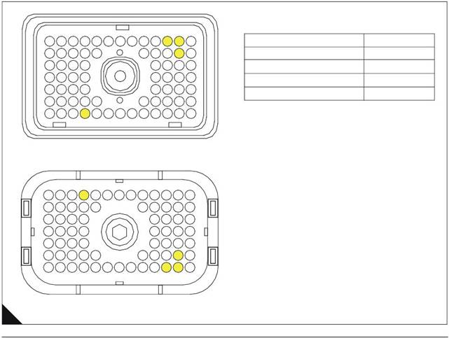 4
4
2800 Series
Test step
Step 5: Check that control voltage is present on the engine
Measure the voltage between pin-24 (+5 V) and pin-20
(Return) on the engine customer interface connector (if fitted)
or J1 pin 15 (+5V) and J1 pin 3 (Return) if a customer interface
connector is not fitted.
The voltage should measure between 0.5 and 4.5 Volts DC.
Result
Action
The electrical circuit is
correct.
Check that the configuration
parameters in the service
tool have analogue speed
control selected and that the
correct speed range is set.
STOP.
Go to step 6.
Step 6: Check that control voltage is present on the external speed control
Measure the signal voltage at the slider of the potentiometer or
the output of the speed control device.
There is a fault in the wiring
between the speed control
and the engine.
Investigate and repair as
necessary.
STOP.
There is a fault in the speed
control potentiometer or
device.
Repair or renew as
necessary.
STOP.
ECM terminal connections
Note: Using ECM connector P1.
13
12
11
10
9
8
7
6
5
4
3
2
1
Function
Pin Location
23
22
21 20
19
18
17
16
15
14
+5 V
2
31
39
47
57
30
38
46
56
29 28
37 36
45 44
55 54
53
52
27 26
35 34
43 42
51 50
25
33
41
49
24
32
40
48
Analogue Speed Input
Analogue Ground
- Battery (Cable Screen)
1
14
B
Wire side
HA0022
148
![]()
|
Special tools
Required service tools
5
|
Part No. |
Description |
|
- |
IBM PC compatible Minimum - Pentium 100 MHz processor or greater, 32 Mb RAM, 200 Mb of available hard disk space, VGA monitor or display, CD-ROM, 3.5 in 1.44 Mb diskette drive, Windows 95 or greater, Windows NT, Windows 2000, RS232 port with 16550AF UART, Built in pointing device or mouse. Recommended - Pentium 200 MHz processor, 64 Mb RAM, 1Gb of available hard disk space, Super VGA monitor or display, 12X CD-ROM, 3.5 in 1.44 Mb diskette drive, Windows 95 or greater, Windows NT, Windows 2000, RS232 port with 16550AF UART, Built in pointing device or mouse. |
|
- |
Single user license for TIPSS All engine data subscription |
|
27610164 |
Communi cation adapter II group (Communicati on adapter II, harness cables, software program, users manual and storage case) |
|
27610165 |
Communication adapter |
|
27610167 |
Communication adapter software |
|
27610168 |
Connector cable (connects communication adapter to diagnostic connector) |
|
27610169 |
RS232 cable (connects communication adapter to PC) |
|
CH11169 |
Terminal removal tool (16 and 18 AWG wire) used for removing pin and socket terminals |
|
GE50036 |
Service tool bypass harness |
|
GE50037 |
70-terminal “AMP” breakout T |
|
GE50038 |
Engine timing probe |
|
GE50039 |
Ti ming probe adapter |
|
GE50040 |
Deutsch “DT” timing probe cable |
149
![]() 5
5
Optional service tools
2800 Series
|
Part No. |
Description |
|
27610181 |
Harness repair tool kit (includes cri mping tool) |
|
27610182 |
Harness repair tool kit top-up |
|
GE50041 |
3-Pin "DT" breakout T (breakout T harness is inserted in series between a harness jack and plug to permit voltage measurement on an operating system) |
|
GE50042 |
Signal reading probes |
|
CH11148 |
Turning tool permits turning engine by hand |
400-100-8969???15088860848
0574-26871589? 15267810868
0574-26886646? 15706865167
0574-26871569 18658287286